SHOCK ABSORBING PAD REMOVAL/INSTALLATION
id091700453300
4SD
Front
1. Set the wheel blocks for both the front and rear wheels (without electric parking brake).
2. Disconnect the negative battery cable. (See NEGATIVE BATTERY CABLE DISCONNECTION/CONNECTION [MZR 1.6].) (See NEGATIVE BATTERY CABLE DISCONNECTION/CONNECTION [SKYACTIV-G 1.5, SKYACTIV-G 2.0, SKYACTIV-G 2.5].)
3. Shift the selector lever from the P position to the D position (ATX).
4. Remove the following parts:
- (1) Sunroof seaming welt (with sunroof system) (See SUNROOF UNIT REMOVAL/INSTALLATION.)
- (2) A-pillar trim (See A-PILLAR TRIM REMOVAL/INSTALLATION.)
- (3) Sunvisor (See SUNVISOR REMOVAL/INSTALLATION.)
- (4) Front map light (dual light type) (See FRONT MAP LIGHT REMOVAL/INSTALLATION.)
- (5) Assist handle (See ASSIST HANDLE REMOVAL/INSTALLATION.)
- (6) Front scuff plate (See FRONT SCUFF PLATE REMOVAL/INSTALLATION.)
- (7) Rear scuff plate (See REAR SCUFF PLATE REMOVAL/INSTALLATION.)
- (8) B-pillar lower trim (See B-PILLAR LOWER TRIM REMOVAL/INSTALLATION.)
- (9) Adjust anchor cover (See FRONT SEAT BELT REMOVAL/INSTALLATION.)
- (10) Upper anchor installation bolt on the seat belt (See FRONT SEAT BELT REMOVAL/INSTALLATION.)
- (11) B-pillar upper trim (See B-PILLAR UPPER TRIM REMOVAL/INSTALLATION.)
- (12) C-pillar trim (See C-PILLAR TRIM REMOVAL/INSTALLATION.)
- (13) Upper panel (See UPPER PANEL REMOVAL.) (See UPPER PANEL INSTALLATION.)
- (14) Rear console (See REAR CONSOLE REMOVAL/INSTALLATION.)
- (15) Shift lever knob (MTX) (See MANUAL TRANSAXLE SHIFT MECHANISM REMOVAL/INSTALLATION [F35M-R].) (See MANUAL TRANSAXLE SHIFT MECHANISM REMOVAL/INSTALLATION [C66M-R].) (See MANUAL TRANSAXLE SHIFT MECHANISM REMOVAL/INSTALLATION [D66M-R].) (See MANUAL TRANSAXLE SHIFT MECHANISM REMOVAL/INSTALLATION [F66M-R].)
- (16) Selector lever knob (ATX) (See AUTOMATIC TRANSAXLE SHIFT MECHANISM REMOVAL/INSTALLATION.)
- (17) Shift panel (See SHIFT PANEL REMOVAL/INSTALLATION.)
- (18) Front console box (without electric parking brake) (See FRONT CONSOLE BOX REMOVAL/INSTALLATION.)
- (19) CD player (with CD player) (See CD PLAYER REMOVAL.) (See CD PLAYER INSTALLATION.)
- (20) DVD/CD player (with DVD/CD player) (See DVD/CD PLAYER REMOVAL.) (See DVD/CD PLAYER INSTALLATION.)
- (21) Glove compartment (See GLOVE COMPARTMENT REMOVAL/INSTALLATION.)
- (22) Decoration panel (See DECORATION PANEL REMOVAL/INSTALLATION.)
- (23) Side wall (See SIDE WALL REMOVAL/INSTALLATION.)
- (24) Front console (See FRONT CONSOLE REMOVAL/INSTALLATION.)
- (25) Headliner (See HEADLINER REMOVAL/INSTALLATION.)
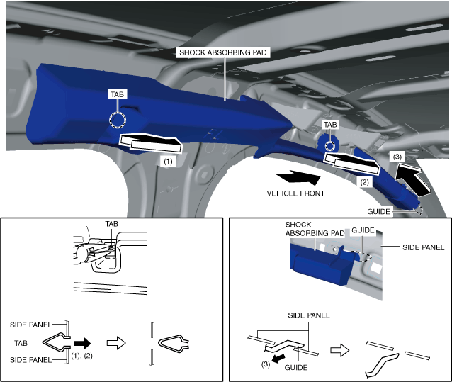
5. Pinch the tab using pincers, remove the tab in the direction of the arrow (1) shown in the figure.
6. Pinch the tab using pincers, remove the tab in the direction of the arrow (2) shown in the figure.
7. Pull the shock absorbing pad in the direction of the arrow (3) and remove it while detaching the guide.
8. Install in the reverse order of removal.
Rear
1. Set the wheel blocks for both the front and rear wheels (without electric parking brake).
2. Disconnect the negative battery cable. (See NEGATIVE BATTERY CABLE DISCONNECTION/CONNECTION [MZR 1.6].) (See NEGATIVE BATTERY CABLE DISCONNECTION/CONNECTION [SKYACTIV-G 1.5, SKYACTIV-G 2.0, SKYACTIV-G 2.5].)
3. Shift the selector lever from the P position to the D position (ATX).
4. Remove the following parts:
- (1) Sunroof seaming welt (with sunroof system) (See SUNROOF UNIT REMOVAL/INSTALLATION.)
- (2) A-pillar trim (See A-PILLAR TRIM REMOVAL/INSTALLATION.)
- (3) Sunvisor (See SUNVISOR REMOVAL/INSTALLATION.)
- (4) Front map light (dual light type) (See FRONT MAP LIGHT REMOVAL/INSTALLATION.)
- (5) Assist handle (See ASSIST HANDLE REMOVAL/INSTALLATION.)
- (6) Front scuff plate (See FRONT SCUFF PLATE REMOVAL/INSTALLATION.)
- (7) Rear scuff plate (See REAR SCUFF PLATE REMOVAL/INSTALLATION.)
- (8) B-pillar lower trim (See B-PILLAR LOWER TRIM REMOVAL/INSTALLATION.)
- (9) Adjust anchor cover (See FRONT SEAT BELT REMOVAL/INSTALLATION.)
- (10) Upper anchor installation bolt on the seat belt (See FRONT SEAT BELT REMOVAL/INSTALLATION.)
- (11) B-pillar upper trim (See B-PILLAR UPPER TRIM REMOVAL/INSTALLATION.)
- (12) C-pillar trim (See C-PILLAR TRIM REMOVAL/INSTALLATION.)
- (13) Upper panel (See UPPER PANEL REMOVAL.) (See UPPER PANEL INSTALLATION.)
- (14) Rear console (See REAR CONSOLE REMOVAL/INSTALLATION.)
- (15) Shift lever knob (MTX) (See MANUAL TRANSAXLE SHIFT MECHANISM REMOVAL/INSTALLATION [F35M-R].) (See MANUAL TRANSAXLE SHIFT MECHANISM REMOVAL/INSTALLATION [C66M-R].) (See MANUAL TRANSAXLE SHIFT MECHANISM REMOVAL/INSTALLATION [D66M-R].) (See MANUAL TRANSAXLE SHIFT MECHANISM REMOVAL/INSTALLATION [F66M-R].)
- (16) Selector lever knob (ATX) (See AUTOMATIC TRANSAXLE SHIFT MECHANISM REMOVAL/INSTALLATION.)
- (17) Shift panel (See SHIFT PANEL REMOVAL/INSTALLATION.)
- (18) Front console box (without electric parking brake) (See FRONT CONSOLE BOX REMOVAL/INSTALLATION.)
- (19) CD player (with CD player) (See CD PLAYER REMOVAL.) (See CD PLAYER INSTALLATION.)
- (20) DVD/CD player (with DVD/CD player) (See DVD/CD PLAYER REMOVAL.) (See DVD/CD PLAYER INSTALLATION.)
- (21) Glove compartment (See GLOVE COMPARTMENT REMOVAL/INSTALLATION.)
- (22) Decoration panel (See DECORATION PANEL REMOVAL/INSTALLATION.)
- (23) Side wall (See SIDE WALL REMOVAL/INSTALLATION.)
- (24) Front console (See FRONT CONSOLE REMOVAL/INSTALLATION.)
- (25) Headliner (See HEADLINER REMOVAL/INSTALLATION.)
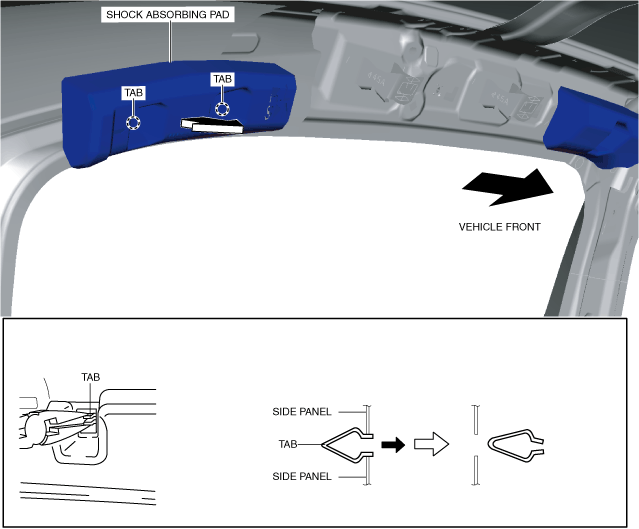
5. Pinch the tabs using pincers, remove the tabs, then remove the shock absorbing pad in the direction of the arrow shown in the figure.
6. Install in the reverse order of removal.
5HB
Front
1. Set the wheel blocks for both the front and rear wheels (without electric parking brake).
2. Disconnect the negative battery cable. (See NEGATIVE BATTERY CABLE DISCONNECTION/CONNECTION [MZR 1.6].) (See NEGATIVE BATTERY CABLE DISCONNECTION/CONNECTION [SKYACTIV-G 1.5, SKYACTIV-G 2.0, SKYACTIV-G 2.5].)
3. Shift the selector lever from the P position to the D position (ATX).
4. Remove the following parts:
- (1) Sunroof seaming welt (with sunroof system) (See SUNROOF UNIT REMOVAL/INSTALLATION.)
- (2) A-pillar trim (See A-PILLAR TRIM REMOVAL/INSTALLATION.)
- (3) Sunvisor (See SUNVISOR REMOVAL/INSTALLATION.)
- (4) Front map light (dual light type) (See FRONT MAP LIGHT REMOVAL/INSTALLATION.)
- (5) Assist handle (See ASSIST HANDLE REMOVAL/INSTALLATION.)
- (6) Front scuff plate (See FRONT SCUFF PLATE REMOVAL/INSTALLATION.)
- (7) Rear scuff plate (See REAR SCUFF PLATE REMOVAL/INSTALLATION.)
- (8) B-pillar lower trim (See B-PILLAR LOWER TRIM REMOVAL/INSTALLATION.)
- (9) Adjust anchor cover (See FRONT SEAT BELT REMOVAL/INSTALLATION.)
- (10) Upper anchor installation bolt on the seat belt (See FRONT SEAT BELT REMOVAL/INSTALLATION.)
- (11) B-pillar upper trim (See B-PILLAR UPPER TRIM REMOVAL/INSTALLATION.)
- (12) Rear package tray (See REAR PACKAGE TRAY REMOVAL/INSTALLATION.)
- (13) Trunk covering (See TRUNK COVERING REMOVAL/INSTALLATION.)
- (14) Trunk board (See TRUNK BOARD REMOVAL/INSTALLATION.)
- (15) Trunk end trim (See TRUNK END TRIM REMOVAL/INSTALLATION.)
- (16) Trunk side upper trim (See TRUNK SIDE UPPER TRIM REMOVAL/INSTALLATION.)
- (17) Trunk side trim (LH only) (See TRUNK SIDE TRIM REMOVAL/INSTALLATION.)
- (18) C-pillar trim (See C-PILLAR TRIM REMOVAL/INSTALLATION.)
- (19) Upper panel (See UPPER PANEL REMOVAL.) (See UPPER PANEL INSTALLATION.)
- (20) Rear console (See REAR CONSOLE REMOVAL/INSTALLATION.)
- (21) Shift lever knob (MTX) (See MANUAL TRANSAXLE SHIFT MECHANISM REMOVAL/INSTALLATION [F35M-R].) (See MANUAL TRANSAXLE SHIFT MECHANISM REMOVAL/INSTALLATION [C66M-R].) (See MANUAL TRANSAXLE SHIFT MECHANISM REMOVAL/INSTALLATION [F66M-R].)
- (22) Selector lever knob (ATX) (See AUTOMATIC TRANSAXLE SHIFT MECHANISM REMOVAL/INSTALLATION.)
- (23) Shift panel (See SHIFT PANEL REMOVAL/INSTALLATION.)
- (24) Front console box (without electric parking brake) (See FRONT CONSOLE BOX REMOVAL/INSTALLATION.)
- (25) CD player (with CD player) (See CD PLAYER REMOVAL.) (See CD PLAYER INSTALLATION.)
- (26) DVD/CD player (with DVD/CD player) (See DVD/CD PLAYER REMOVAL.) (See DVD/CD PLAYER INSTALLATION.)
- (27) Glove compartment (See GLOVE COMPARTMENT REMOVAL/INSTALLATION.)
- (28) Decoration panel (See DECORATION PANEL REMOVAL/INSTALLATION.)
- (29) Side wall (See SIDE WALL REMOVAL/INSTALLATION.)
- (30) Front console (See FRONT CONSOLE REMOVAL/INSTALLATION.)
- (31) Headliner (See HEADLINER REMOVAL/INSTALLATION.)
5. Pinch the tab using pincers, remove the tab in the direction of the arrow (1) shown in the figure.
6. Pinch the tab using pincers, remove the tab in the direction of the arrow (2) shown in the figure.
7. Pull the shock absorbing pad in the direction of the arrow (3) and remove it while detaching the guide.
8. Install in the reverse order of removal.
Rear
1. Set the wheel blocks for both the front and rear wheels (without electric parking brake).
2. Disconnect the negative battery cable. (See NEGATIVE BATTERY CABLE DISCONNECTION/CONNECTION [MZR 1.6].) (See NEGATIVE BATTERY CABLE DISCONNECTION/CONNECTION [SKYACTIV-G 1.5, SKYACTIV-G 2.0, SKYACTIV-G 2.5].)
3. Shift the selector lever from the P position to the D position (ATX).
4. Remove the following parts:
- (1) Sunroof seaming welt (with sunroof system) (See SUNROOF UNIT REMOVAL/INSTALLATION.)
- (2) A-pillar trim (See A-PILLAR TRIM REMOVAL/INSTALLATION.)
- (3) Sunvisor (See SUNVISOR REMOVAL/INSTALLATION.)
- (4) Front map light (dual light type) (See FRONT MAP LIGHT REMOVAL/INSTALLATION.)
- (5) Assist handle (See ASSIST HANDLE REMOVAL/INSTALLATION.)
- (6) Front scuff plate (See FRONT SCUFF PLATE REMOVAL/INSTALLATION.)
- (7) Rear scuff plate (See REAR SCUFF PLATE REMOVAL/INSTALLATION.)
- (8) B-pillar lower trim (See B-PILLAR LOWER TRIM REMOVAL/INSTALLATION.)
- (9) Adjust anchor cover (See FRONT SEAT BELT REMOVAL/INSTALLATION.)
- (10) Upper anchor installation bolt on the seat belt (See FRONT SEAT BELT REMOVAL/INSTALLATION.)
- (11) B-pillar upper trim (See B-PILLAR UPPER TRIM REMOVAL/INSTALLATION.)
- (12) Rear package tray (See REAR PACKAGE TRAY REMOVAL/INSTALLATION.)
- (13) Trunk covering (See TRUNK COVERING REMOVAL/INSTALLATION.)
- (14) Trunk board (See TRUNK BOARD REMOVAL/INSTALLATION.)
- (15) Trunk end trim (See TRUNK END TRIM REMOVAL/INSTALLATION.)
- (16) Trunk side upper trim (See TRUNK SIDE UPPER TRIM REMOVAL/INSTALLATION.)
- (17) Trunk side trim (LH only) (See TRUNK SIDE TRIM REMOVAL/INSTALLATION.)
- (18) C-pillar trim (See C-PILLAR TRIM REMOVAL/INSTALLATION.)
- (19) Upper panel (See UPPER PANEL REMOVAL.) (See UPPER PANEL INSTALLATION.)
- (20) Rear console (See REAR CONSOLE REMOVAL/INSTALLATION.)
- (21) Shift lever knob (MTX) (See MANUAL TRANSAXLE SHIFT MECHANISM REMOVAL/INSTALLATION [F35M-R].) (See MANUAL TRANSAXLE SHIFT MECHANISM REMOVAL/INSTALLATION [C66M-R].) (See MANUAL TRANSAXLE SHIFT MECHANISM REMOVAL/INSTALLATION [F66M-R].)
- (22) Selector lever knob (ATX) (See AUTOMATIC TRANSAXLE SHIFT MECHANISM REMOVAL/INSTALLATION.)
- (23) Shift panel (See SHIFT PANEL REMOVAL/INSTALLATION.)
- (24) Front console box (without electric parking brake) (See FRONT CONSOLE BOX REMOVAL/INSTALLATION.)
- (25) CD player (with CD player) (See CD PLAYER REMOVAL.) (See CD PLAYER INSTALLATION.)
- (26) DVD/CD player (with DVD/CD player) (See DVD/CD PLAYER REMOVAL.) (See DVD/CD PLAYER INSTALLATION.)
- (27) Glove compartment (See GLOVE COMPARTMENT REMOVAL/INSTALLATION.)
- (28) Decoration panel (See DECORATION PANEL REMOVAL/INSTALLATION.)
- (29) Side wall (See SIDE WALL REMOVAL/INSTALLATION.)
- (30) Front console (See FRONT CONSOLE REMOVAL/INSTALLATION.)
- (31) Headliner (See HEADLINER REMOVAL/INSTALLATION.)
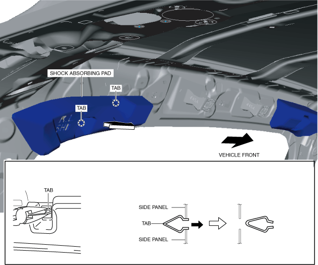
5. Pinch the tabs using pincers, remove the tabs, then remove the shock absorbing pad in the direction of the arrow shown in the figure.
6. Install in the reverse order of removal.