 |
am6zzw00008173
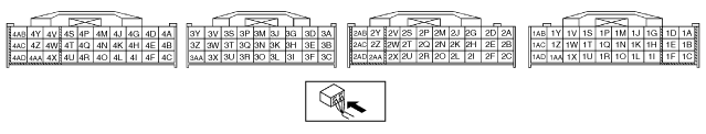
PCM INSPECTION [LF, L3]
id0140008025a6
Using SST (WDS or Equivalent)
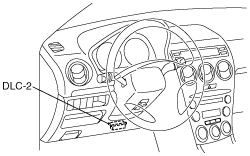
1. Connect the SST (WDS or equivalent) to the DLC-2.
am6zzw00008173
|
2. Turn the ignition switch to ON position.
3. Measure the PID value.
PID/DATA monitor table (reference)
|
Monitor item (Definition) |
Unit/Condition |
Condition/Specification (Reference) |
Action |
PCM terminal |
|
|---|---|---|---|---|---|
|
ACCS (A/C relay)
|
ON/OFF
|
Ignition switch ON: OFF
A/C switch ON and fan switch ON at idle: ON
|
Inspect following PIDs: RPM, TP, ECT, ACSW, TR.
Inspect A/C relay.
|
4O
|
|
|
ACSW (A/C switch)
|
ON/OFF
|
A/C switch and fan switch ON at ignition switch ON: ON
A/C switch OFF at ignition switch ON: OFF
|
Inspect A/C switch.
|
1AC
|
|
|
ALTF (Generator field coil control duty value)
|
%
|
Ignition switch ON: 0%
Idle: 0—100%
Just after A/C switch ON and fan switch ON at idle: Duty value rises
|
Inspect following PIDs: IAT, ECT, RPM, VPWR, ALTT V.
Inspect generator.
|
1AD
|
|
|
ALTT V (Generator output voltage)
|
V
|
Ignition switch ON: 0 V
Idle: Approx. 14.9 V*1 (E/L not operating)
|
Inspect generator.
|
1AA
|
|
|
ARPMDES
(Target engine speed)
|
RPM
|
MTX
No load: 650 rpm
E/L operating: 700 rpm
P/S operating: 700 rpm
A/C ON: 750 rpm
ATX
No load: 700 rpm
E/L operating: 700 rpm
P/S operating: 700 rpm
A/C ON: 700 rpm*2, 750 rpm*3
|
Inspect following PIDs: IAT, RPM, MAP, ECT, MAF, TP, INGEAR, ACSW, TR, PSP, ALTT V.
Inspect IAC valve.
Inspect CKP sensor.
|
—
|
|
|
AST (After start timer)
|
Time
|
—
|
—
|
—
|
|
|
BOO
(Brake switch)
|
ON/OFF
|
Brake pedal depressed: ON
Brake pedal released: OFF
|
Inspect brake switch.
(See BRAKE SWITCH INSPECTION)
|
1K
|
|
|
CHRGLP (Generator warning light)
|
ON/OFF
|
Ignition switch ON: ON
Idle: OFF
|
Perform applicable DTC troubleshooting.
(See DTC TABLE [LF, L3])
|
—
|
|
|
COLP (Refrigerant pressure switch (middle))*4
|
ON/OFF
|
Refrigerant pressure switch (middle) ON *2 at idle: ON
Refrigerant pressure switch (middle) OFF*3 at idle: OFF
|
Inspect refrigerant pressure switch.
|
1Q
|
|
|
CPP
(Clutch pedal position)
|
ON/OFF
|
Clutch pedal depressed: ON
Clutch pedal released: OFF
|
Inspect clutch switch.
|
1R
|
|
|
CPP/PNP (Shift lever position)
|
ON/OFF
|
Neutral position: ON
Others: OFF
|
Inspect neutral switch.
|
1W
|
|
|
DTCCNT (Number of DTC detected)
|
—
|
—
|
Perform applicable DTC troubleshooting.
(See DTC TABLE [LF, L3])
|
—
|
|
|
ECT (Engine coolant temperature)
|
°C
|
°F
|
ECT 20 °C {68 °F}: 20 °C {68 °F}
ECT 60 °C {140 °F}: 60 °C {140 °F}
|
Inspect ECT sensor.
|
1M
|
|
V
|
ECT 20 °C {68 °F}: 3.04—3.14 V
ECT 60 °C {140 °F}: 1.29—1.39 V
|
||||
|
EVAPCP (Purge solenoid valve duty value)
|
%
|
Ignition switch ON: 0%
Idle: 0%
|
Inspect following PIDs: IAT, RPM, ECT, MAF, O2S11,BARO, INGEAR, TR, VPWR.
|
4U
|
|
|
FAN1
(Cooling fan control)
|
ON/OFF
|
ECT below 100 °C {212 °F}: OFF
Others: ON
|
Inspect following PIDs: RPM, TP, ECT, ACSW, COLP, TEST.
Inspect cooling fan relay.
(See RELAY INSPECTION)
|
4L
|
|
|
FAN2
(Cooling fan control)
|
ON/OFF
|
ECT below 108 °C {226 °F}: OFF
A/C operating, refrigerant pressure switch (middle) is OFF, and ECT below 108 °C {226 °F}: OFF
Others: ON
|
Inspect following PIDs: RPM, TP, ECT, ACSW, COLP, TEST.
Inspect cooling fan relay.
(See RELAY INSPECTION)
|
4F
|
|
|
FAN3
(Cooling fan control)
|
ON/OFF
|
ECT below 100 °C {212 °F}: OFF
A/C operating, refrigerant pressure switch (middle) is ON, and ECT below 108 °C {226 °F}: OFF
Other: ON
|
Inspect following PIDs: RPM, TP, ECT, ACSW, COLP, TEST.
Inspect cooling fan relay.
(See RELAY INSPECTION)
|
4B
|
|
|
FDPDTC
(Pending code caused FFD storage)
|
—
|
—
|
Perform applicable DTC troubleshooting.
(See DTC TABLE [LF, L3])
|
—
|
|
|
FP (Fuel pump relay)
|
ON/OFF
|
Ignition switch ON: OFF
Idle: ON
Cranking: ON
|
Inspect following PIDs: RPM.
Inspect fuel pump relay.
(See RELAY INSPECTION)
|
4P*5
|
|
|
4Q*6
|
|||||
|
FUELPW (Fuel injector duration)
|
TIME
|
Ignition switch ON: 0 ms
Idle (after warm up): approx. 2.5 ms
|
Inspect following PIDs: IAT, MAF, TP, MAP, ECT, RPM, O2S11, O2S12, INGEAR, TR, PSP, ACSW, VPWR, ALTT V.
Inspect fuel injector.
(See RELAY INSPECTION)
|
4W, 4Z, 4AA, 4AD
|
|
|
FUELSYS
(Fuel system status)
|
Open loop/Closed loop
|
Ignition switch ON: Open loop
Idle (after warm up): Open loop
|
Inspect following PIDs: IAT, MAF, TP, MAP, ECT, RPM, O2S11, O2S12, INGEAR, TR, PSP, ACSW, VPWR, ALTT V.
Inspect fuel injector.
(See RELAY INSPECTION)
|
—
|
|
|
GENVDSD
(Generator voltage desired)
|
V
|
Ignition switch ON: 0 V
Idle: Approx. 14.9 V*1 (E/L not operating)
|
Perform applicable DTC troubleshooting.
(See DTC TABLE [LF, L3])
|
—
|
|
|
HTR11*8
(HO2S heater (front))
|
ON/OFF
|
Idle (after warm up): ONÛOFF
|
Inspect following PIDs: IAT, MAF, TP, ECT, RPM, ACSW.
|
4A
|
|
|
HTR12*8
(HO2S heater (rear))
|
ON/OFF
|
Ignition switch ON: ON (HO2S heater operated)
Idle: ON (HO2S heater operated)
|
Inspect following PIDs: IAT, MAF, ECT, RPM, ACSW.
|
4D
|
|
|
IAC (IAC valve)
|
%
|
Ignition switch ON: 0%
Idle: Approx. 20% (ECT: approx. 90°C {194 °F} and E/L not operating)
|
Inspect following PIDs: IAT, RPM, MAP, ECT, MAF, TP, INGEAR, TR, PSP, ACSW.
Inspect IAC valve.
|
4G, 4J
|
|
|
IASV*7
(Variable air duct control solenoid valve)
|
ON/OFF
|
ECT is above 70 °C {158 °F}, engine speed is above 5,800 rpm, and TP opening angle is above 50%: ON
Others: OFF
|
Inspect following PIDs: ECT, RPM, TP.
Inspect VAD control solenoid valve.
|
4C
|
|
|
IAT
(Intake air temperature)
|
°C
|
°F
|
IAT 20 °C {68 °F}: 20 °C {68 °F}
IAT 30 °C {86 °F}: 30 °C {86 °F}
|
Inspect IAT sensor.
|
2E
|
|
V
|
IAT 20 °C {68 °F}: 2.4—2.6 V
IAT 30 °C {86 °F}: 1.7—1.9 V
|
||||
|
IMRC (Variable tumble control solenoid valve)
|
ON/OFF
|
Engine speed is below approx. 3,500 rpm: ON
Others: OFF
|
Inspect following PIDs: TP, ECT, RPM.
Inspect VTCS solenoid valve.
|
4T
|
|
|
IMTV*7 (Variable Intake-air control solenoid valve)
|
ON/OFF
|
Engine speed is below approx. 4,350 rpm: ON
Others: OFF
|
Inspect following PIDs: RPM.
Inspect VIS control solenoid valve.
|
4R
|
|
|
INGEAR (Load/no load condition)
|
ON/OFF
|
CPP or CPP/PNP is ON: OFF
Others: ON
|
Perform applicable DTC troubleshooting.
(See DTC TABLE [LF, L3])
|
1R, 1W
|
|
|
IVS (CTP condition)
|
ON/OFF
|
CTP: ON
Others: OFF
|
Perform applicable DTC troubleshooting.
(See DTC TABLE [LF, L3])
|
2A
|
|
|
KNOCKR (Knocking retard)
|
ANGLE
|
Ignition switch ON: 0 DEG
Idle: 0 DEG
|
Inspect knock sensor.
|
2P, 2S
|
|
|
LOAD (Engine load)
|
%
|
Ignition switch ON: 0%
Idle (After warm up): approx.19%
|
Inspect MAF sensor.
|
—
|
|
|
LONGFT1*8 (long term fuel trim)
|
%
|
Idle (after warm up): approx.–14—14%
|
Perform applicable DTC troubleshooting.
(See DTC TABLE [LF, L3])
|
—
|
|
|
MAF (Mass airflow)
|
g/s
|
Ignition switch ON: approx. 0 g/s
Idle (After warm up): 1.5 g/s
|
Inspect MAF sensor.
|
1P
|
|
|
V
|
Ignition switch ON: approx. 0.7 V
Idle (After warm up): approx. 1.3 V
|
||||
|
MAP (Manifold absolute pressure)
|
kPa
|
Ignition switch ON (At sea level): approx. 101 kPa
|
Inspect MAP sensor.
|
1J
|
|
|
V
|
Ignition switch ON (At sea level): approx. 4.1 V
|
||||
|
MIL (Malfunction indicator lamp)
|
ON/OFF
|
Ignition switch ON: ON
Idle: OFF
|
Perform applicable DTC troubleshooting.
(See DTC TABLE [LF, L3])
|
—
|
|
|
MIL_DIS (Distance trabelled distance since the MIL illuminated)
|
Metreage
|
No DTC: 0 km {0 mph}
DTC detected: Not 0 km {0 mph}
|
Perform applicable DTC troubleshooting.
(See DTC TABLE [LF, L3])
|
—
|
|
|
O2S11*8
(Front oxygen sensor)
|
V
|
Ignition switch ON: 0—1.0 V
Idle (After warm up): 0—1.0 V
Acceleration (After warm up):
0.5—1.0 V
Deceleration (After warm up):
0—0.5 V
|
Inspect HO2S (front).
|
1AB
|
|
|
O2S12*8
(Rear oxygen sensor)
|
V
|
Idle (After warm up): approx 0.6 V
|
Inspect HO2S (rear).
|
1Y
|
|
|
PSP (Power steering pressure switch)
|
ON/OFF
|
Steering wheel in straight ahead position: OFF
Others: ON
|
Inspect PSP switch.
|
1Z
|
|
|
RFCFLAG (Readiness function code)
|
—
|
Before running PCM adaptive memory procedure drive mode: Not Learnt
After running PCM adaptive memory procedure drive mode: Learnt
|
Run PCM adaptive memory procedure drive mode.
(See OBD DRIVE MODE [LF, L3])
|
—
|
|
|
RO2FT1*8
(Rear oxygen sensor fuel trim)
|
—
|
Idle (After warm up): approx.–0.03—0.03
|
Perform applicable DTC troubleshooting.
(See DTC TABLE [LF, L3])
|
—
|
|
|
RPM (Engine speed)
|
rpm
|
MTX
No load: 600—700 rpm
E/L operating: 650—750 rpm
P/S operating: 650—750 rpm
A/C ON: 700—800 rpm
ATX
No load: 650—750 rpm
E/L operating: 650—750 rpm
P/S operating: 650—750 rpm
A/C ON: 650—750 rpm*2, 700—800 rpm*3
|
Inspect CKP sensor.
|
2D, 2G
|
|
|
SEGRP*8
(EGR valve (stepping motor) position)
|
STEP
|
Ignition switch ON: 0 step
Idle: 0 step
Cranking: 0—60 steps
|
Inspect following PIDs: MAF, TP, ECT, RPM, VSS.
Inspect EGR valve.
|
4E, 4H, 4K, 4N
|
|
|
SHRTFT1*8
(Short term fuel trim)
|
%
|
Idle (After warm up): approx.–30—25%
|
Perform applicable DTC troubleshooting.
(See DTC TABLE [LF, L3])
|
—
|
|
|
SPARKADV (Ignition timing)
|
BTDC
|
Ignition switch ON: BTDC 0°
Idle: BTDC approx. 10°
|
Inspect following PIDs: MAF, TP, ECT, RPM, INGEAR, TR, PSP, ACSW, VPWR.
Inspect ignition timing.
|
2J, 2M
|
|
|
TEST (Test mode)
|
ON/OFF
|
—
|
—
|
—
|
|
|
TP (TP)
|
%
|
CTP: 13—23%
WOT: 86—96%
|
Inspect TP sensor.
|
2A
|
|
|
V
|
CTP: 0.65—1.15 V
WOT: 4.3—4.8 V
|
||||
|
TPCT
(TP sensor voltage at CTP)
|
V
|
0.65—1.15 V
|
Inspect TP sensor.
|
2A
|
|
|
VPWR (Battery positive voltage)
|
V
|
Ignition switch ON: B+
|
Inspect main relay.
(See RELAY INSPECTION)
Inspect battery.
|
2Y, 2Z
|
|
|
VR V*9
(Variable resistor)
|
V
|
Ignition switch ON: 1—4 V
|
Inspect variable resistor.
Inspect battery.
|
1AB
|
|
|
VSS (Vehicle speed)
|
km/h
|
MPH
|
Vehicle speed 20 km/h {12 mph}:
20 km/h {12 mph}
Vehicle speed 40 km/h {25 mph}:
20 km/h {12 mph}
|
Perform applicable DTC troubleshooting.
(See DTC TABLE [LF, L3])
|
2I, 2L
(MTX)
|
|
3C
(ATX)
|
|||||
|
VT DUTY1*7
|
ANGLE
|
Idle: 0°
|
Inspect following PIDs: TP, ECT, RPM.
Inspect OCV.
|
4M
|
|
|
%
|
Idle: 0%
|
||||
Without Using the SST
1. Measure the voltage at each terminal.
Terminal voltage table (Reference)
am6zzw00008174
|
|
Terminal |
Signal |
Connected to |
Test condition |
Voltage (V) |
Action |
|
|---|---|---|---|---|---|---|
|
1A
|
IGT1
|
Ignition coil (No. 1, 4 cylinders)
|
• Inspect using the wave profile.
|
• Inspect ignition coil
• Inspect related harness
|
||
|
1B
|
IGT2
|
Ignition coil (No. 2, 3 cylinders)
|
• Inspect using the wave profile.
|
• Inspect ignition coil
• Inspect related harness
|
||
|
1C
|
GND
|
GND
|
Under any condition
|
Below 1.0
|
• Inspect related harness
|
|
|
1D
|
GND
|
GND
|
Under any condition
|
Below 1.0
|
• Inspect related harness
|
|
|
1E
|
—
|
—
|
—
|
—
|
—
|
|
|
1F
|
—
|
—
|
—
|
—
|
—
|
|
|
1G
|
—
|
—
|
—
|
—
|
—
|
|
|
1H
|
—
|
—
|
—
|
—
|
—
|
|
|
1I
|
—
|
—
|
—
|
—
|
—
|
|
|
1J
|
Manifold absolute pressure
|
MAP sensor
|
Ignition switch ON (Engine OFF)
|
Approx. 4.1
|
• Inspect MAP sensor
• Inspect related harness
|
|
|
Idle
|
Approx. 1.5
|
|||||
|
1K
|
Brake
|
Brake switch
|
Brake pedal depressed
|
B+
|
• Inspect brake switch
• Inspect related harness
|
|
|
Brake pedal released
|
Below 1.0
|
|||||
|
1L
|
—
|
—
|
—
|
—
|
—
|
|
|
1M
|
ECT
|
ECT sensor
|
Ignition switch ON
|
ECT 20 °C
{68 °F}
|
3.04—3.14
|
• Inspect ECT sensor
• Inspect related harness
|
|
ECT 60 °C
{140 °F}
|
1.29—1.39
|
|||||
|
1N
|
—
|
—
|
—
|
—
|
—
|
|
|
1O
|
—
|
—
|
—
|
—
|
—
|
|
|
1P
|
MAF
|
MAF sensor
|
Ignition switch ON
|
Approx. 0.7
|
• Inspect MAF sensor
• Inspect related harness
|
|
|
Idle (After warm up)
|
Approx. 1.3
|
|||||
|
1Q
|
Refrigerant pressure switch (Middle)
|
Refrigerant pressure switch (Middle)
|
A/C ON
|
Refrigerant pressure is above 1.52 MPa
|
Below 1.0
|
• Inspect refrigerant pressure switch
• Inspect related harness
|
|
Refrigerant pressure is below 1.23 MPa
|
B+
|
|||||
|
1R*1
|
Clutch operation
|
Clutch switch
|
Clutch pedal depressed
|
Below 1.0
|
• Inspect clutch switch
• Inspect related harness
|
|
|
Clutch pedal released
|
B+
|
|||||
|
1S
|
—
|
—
|
—
|
—
|
—
|
|
|
1T
|
—
|
—
|
—
|
—
|
—
|
|
|
1U
|
—
|
—
|
—
|
—
|
—
|
|
|
1V
|
—
|
—
|
—
|
—
|
—
|
|
|
1W
|
Neutral position*1
|
Neutral switch
|
Shift lever is at neutral position
|
Below 1.0
|
• Inspect neutral switch
• Inspect related harness
|
|
|
Shift lever is not at neutral position
|
B+
|
|||||
|
Selector lever position*2
|
TR switch
(Terminal C)
|
Ignition switch ON
|
P range
|
Approx. 4.6
|
• Inspect TR switch
• Inspect related harness
|
|
|
R range
|
Approx. 3.9
|
|||||
|
N range
|
Approx. 3.2
|
|||||
|
D range*3
M range*4
|
Approx. 2.5
|
|||||
|
S range*5
|
Approx. 1.7
|
|||||
|
L range*5
|
Approx. 0.94
|
|||||
|
1X
|
—
|
—
|
—
|
—
|
—
|
|
|
1Y*5
|
HO2S (Rear)
|
HO2S (Rear)
|
Ignition switch ON
|
Approx. 0
|
• Inspect HO2S (rear)
• Inspect related harness
|
|
|
Idle (After warm up)
|
0—1.0
|
|||||
|
1Z
|
PSP
|
PSP switch
|
Idle
|
Steering wheel at straight ahead position
|
B+
|
• Inspect PSP switch
• Inspect power steering system
• Inspect related harness
|
|
While turning steering wheel
|
Below 1.0
|
|||||
|
1AA
|
Generator output voltage
|
Generator
(Terminal P)
|
• Inspect using the wave profile.
|
• Inspect generator
• Inspect related harness
|
||
|
1AB
|
HO2S (Front)*5
|
HO2S (Front)
|
• Inspect using the wave profile.
|
• Inspect HO2S (front)
• Inspect related harness
|
||
|
Variable resistor*6
|
Variable resistor
|
Varies according to the variable resistor adjustment
|
0—4
|
• Inspect variable resistor
• Inspect related harness
|
||
|
1AC
|
A/C on signal
|
Refrigerant pressure switch
|
Idle
|
A/C switch and fan switch on
|
Below 1.0
|
• Inspect refrigerant pressure switch
• Inspect related harness
|
|
A/C switch off
|
B+
|
|||||
|
1AD
|
Generator field coil control
|
Generator
(Terminal D)
|
• Inspect using the wave profile.
|
• Inspect following PIDs: IAT, ECT, RPM, VPWR, ALTT V.
• Inspect generator
• Inspect related harness
|
||
|
2A
|
Throttle position
|
TP sensor
|
Ignition switch ON
|
CTP
|
0.65—1.15
|
• Inspect TP sensor
• Inspect related harness
|
|
WOT
|
4.3—4.8
|
|||||
|
2B
|
—
|
—
|
—
|
—
|
—
|
|
|
2C
|
—
|
—
|
—
|
—
|
—
|
|
|
2D
|
CKP (+)
|
CKP sensor
|
• Inspect using the wave profile.
|
• Inspect CKP sensor
• Inspect related harness
|
||
|
2E
|
IAT
|
MAF/IAT sensor
|
Ignition switch ON
|
IAT 20 °C
{68 °F}
|
2.4—2.6
|
• Inspect IAT sensor
• Inspect related harness
|
|
IAT 30 °C
{86 °F}
|
1.7—1.9
|
|||||
|
2F
|
—
|
—
|
—
|
—
|
—
|
|
|
2G
|
CKP (–)
|
CKP sensor
|
• Inspect using the wave profile.
|
• Inspect CKP sensor
• Inspect related harness
|
||
|
2H
|
Sensor GND
|
MAF/IAT sensor, HO2S (Front, Rear), Variable resistor, ECT sensor, TP sensor, MAP sensor, TFT sensor, TR switch
|
Under any condition
|
Below 1.0
|
• Inspect related harness
|
|
|
2I*7
|
VSS (–)
|
VSS
|
• Inspect using the wave profile.
|
• Inspect VSS sensor
• Inspect related harness
|
||
|
2J
|
CMP (+)
|
CMP sensor
|
• Inspect using the wave profile.
|
• Inspect CMP sensor
• Inspect related harness
|
||
|
2K
|
Constant voltage (Vref)
|
MAP sensor, TP sensor, variable resistor
|
Ignition switch ON
|
Approx. 5.0
|
• Inspect related harness
|
|
|
2L*7
|
VSS (+)
|
VSS
|
• Inspect using the wave profile.
|
• Inspect VSS sensor
• Inspect related harness
|
||
|
2M
|
CMP (–)
|
CMP sensor
|
• Inspect using the wave profile.
|
• Inspect CMP sensor
• Inspect related harness
|
||
|
2N
|
—
|
—
|
—
|
—
|
—
|
|
|
2O
|
—
|
—
|
—
|
—
|
—
|
|
|
2P
|
Knocking (–)
|
Knock sensor
|
Ignition switch ON (Use digital type voltmeter, because measurement voltage will be detected less than true voltage when using analog type voltmeter)
|
Below 1.0
|
• Perform “On-Board Diagnostic Test”
• Inspect related harness
|
|
|
2Q*8
|
Coil (Immobilizer system)
|
Coil
|
Because this terminal is for communication, good/no good judgment by terminal voltage is not possible.
|
• Inspect coil
• Inspect related harness
|
||
|
2R
|
CAN (–)
|
Instrument cluster, ABS HU/CM, ABS/TCS HU/CM, DSC HU/CM
|
Because this terminal is for CAN, good/no good judgment by terminal voltage is not possible.
|
• Inspect related harness
|
||
|
2S
|
Knocking (+)
|
Knock sensor
|
Ignition switch ON (Use digital type voltmeter, because measurement voltage will be detected less than true voltage when using analog type voltmeter)
|
Approx. 4.3
|
• Perform “On-Board Diagnostic Test”
• Inspect related harness
|
|
|
2T*8
|
Coil (Immobilizer system)
|
Coil
|
Because this terminal is for communication, good/no good judgment by terminal voltage is not possible.
|
• Inspect coil
• Inspect related harness
|
||
|
2U
|
CAN (+)
|
Instrument cluster, ABS HU/CM, ABS/TCS HU/CM, DSC HU/CM
|
Because this terminal is for CAN, good/no good judgment by terminal voltage is not possible.
|
• Inspect related harness
|
||
|
2V
|
—
|
—
|
—
|
—
|
—
|
|
|
2W
|
Security light control
|
Instrument cluster (Security light)
|
Security light illuminate
|
Below 1.0
|
• Inspect related harness
|
|
|
Others
|
B+
|
|||||
|
2X
|
Main relay control
|
Main relay
|
Ignition switch OFF
|
Below 1.0
|
• Inspect main relay
(See RELAY INSPECTION)
• Inspect related harness
|
|
|
Ignition switch ON
|
||||||
|
2Y
|
B+
|
Main relay
|
Ignition switch OFF
|
Below 1.0
|
• Inspect battery
• Inspect related harness
|
|
|
Ignition switch ON
|
B+
|
|||||
|
2Z
|
Back-up power supply
|
Battery (Positive terminal)
|
Under any condition
|
B+
|
• Inspect battery
• Inspect related harness
|
|
|
2AA
|
—
|
—
|
—
|
—
|
—
|
|
|
2AB
|
GND
|
GND
|
Under any condition
|
Below 1.0
|
• Inspect related harness
|
|
|
2AC
|
GND
|
GND
|
Under any condition
|
Below 1.0
|
• Inspect related harness
|
|
|
2AD
|
—
|
—
|
—
|
—
|
—
|
|
|
3A
|
—
|
—
|
—
|
—
|
—
|
|
|
3B
|
—
|
—
|
—
|
—
|
—
|
|
|
3C*2
|
Vehicle speed
|
VSS (ATX)
|
• Inspect using the wave profile.
|
• Inspect VSS
• Inspect related harness
|
||
|
3D*2
|
ATF temperature
|
TFT sensor
|
Ignition switch ON
|
TFT 20 °C
{68 °F}
|
Approx. 3.3
|
• Inspect TFT sensor
• Inspect related harness
|
|
TFT 40 °C
{104 °F}
|
Approx. 2.4
|
|||||
|
TFT 60 °C
{140 °F}
|
Approx. 1.5
|
|||||
|
3E
|
—
|
—
|
—
|
—
|
—
|
|
|
3F
|
—
|
—
|
—
|
—
|
—
|
|
|
3G*2
|
Input/turbine speed sensor (+)
|
Input/turbine speed sensor
|
• Inspect using the wave profile.
|
• Inspect input/turbine speed sensor
• Inspect related harness
|
||
|
3H
|
—
|
—
|
—
|
—
|
—
|
|
|
3I
|
—
|
—
|
—
|
—
|
—
|
|
|
3J*2
|
Input/turbine speed sensor (–)
|
Input/turbine speed sensor
|
• Inspect using the wave profile.
|
• Inspect input/turbine speed sensor
• Inspect related harness
|
||
|
3K*2, 4
|
Manual down
|
Down switch
|
Ignition switch ON
|
Detects down-shift operation of selector lever in M range
|
Below 1.0
|
• Inspect down switch
• Inspect related harness
|
|
Others
|
B+
|
|||||
|
3L
|
—
|
—
|
—
|
—
|
—
|
|
|
3M
|
—
|
—
|
—
|
—
|
—
|
|
|
3N*2, 4
|
Manual up
|
Up switch
|
Ignition switch ON
|
Detects up-shift operation of selector lever in M range
|
Below 1.0
|
• Inspect up switch
• Inspect related harness
|
|
Others
|
B+
|
|||||
|
3O
|
—
|
—
|
—
|
—
|
—
|
|
|
3P*2
|
Shift solenoid E control
|
Shift solenoid E
|
Detects TCC operation
|
B+
|
• Inspect shift solenoid E
• Inspect related harness
|
|
|
Others
|
Below 1.0
|
|||||
|
3Q*2
|
HOLD*3
|
HOLD switch
|
Ignition switch ON
|
HOLD switch pushed
|
Below 1.0
|
• Inspect HOLD switch
• Inspect related harness
|
|
Others
|
B+
|
|||||
|
M range*4
|
M range switch
|
Ignition switch ON
|
Manual mode
|
Below 1.0
|
• Inspect M range switch
• Inspect related harness
|
|
|
Others
|
B+
|
|||||
|
3R
|
—
|
—
|
—
|
—
|
—
|
|
|
3S*2
|
Shift solenoid D control
|
Shift solenoid D
|
Selector lever is at P, N position
|
B+
|
• Inspect shift solenoid D
• Inspect related harness
|
|
|
Others
|
Below 1.0
|
|||||
|
3T*2
|
Oil pressure
|
Oil pressure switch
|
Oil pressure switch ON
|
Below 1.0
|
• Inspect oil pressure switch
• Inspect related harness
|
|
|
Oil pressure switch OFF
|
B+
|
|||||
|
3U
|
—
|
—
|
—
|
—
|
—
|
|
|
3V*2
|
Pressure control solenoid (–)
|
Pressure control solenoid valve
|
• Inspect using the wave profile.
|
• Inspect pressure control solenoid valve
• Inspect related harness
|
||
|
3W
|
—
|
—
|
—
|
—
|
—
|
|
|
3X
|
—
|
—
|
—
|
—
|
—
|
|
|
3Y*2
|
Pressure control solenoid (+)
|
Pressure control solenoid valve
|
• Inspect using the wave profile.
|
• Inspect pressure control solenoid valve
• Inspect related harness
|
||
|
3Z
|
—
|
—
|
—
|
—
|
—
|
|
|
3AA
|
—
|
—
|
—
|
—
|
—
|
|
|
4A*4
|
HO2S (Front) heater control
|
HO2S (Front) heater
|
• Inspect using the wave profile.
|
• Inspect HO2S (Front) heater.
• Inspect related harness
|
||
|
4B
|
Cooling fan control
|
Cooling fan relay
|
Idling
|
ECT below 100 °C {212 °F}
|
B+
|
• Inspect cooling fan relay
• Inspect related harness
|
|
A/C operating
|
Below 1.0
|
|||||
|
4C*4
|
VAD control
|
VAD control solenoid valve
|
Ignition switch ON
|
Engine speed below 5,800 rpm
|
B+
|
• Inspect VAD control solenoid valve
• Inspect related harness
|
|
Engine speed above 5,800 rpm
|
Below 1.0
|
|||||
|
4D*5
|
HO2S (Rear) heater control
|
HO2S (Rear) heater
|
Ignition switch ON
|
Engine speed below 4,000 rpm
|
B+
|
• Inspect HO2S (Front) heater.
• Inspect related harness
|
|
Engine speed above 4,000 rpm
|
Below 1.0
|
|||||
|
4E*5
|
EGR valve #1 coil control
|
EGR valve
(terminal E)
|
Ignition switch ON
|
Below 1.0
|
• Inspect EGR valve
• Inspect related harness
|
|
|
Idle
|
Below 1.0
|
|||||
|
4F*10
|
Cooling fan control
|
Cooling fan relay
|
Idling
|
ECT below 100 °C {212 °F}
|
B+
|
• Inspect cooling fan relay
• Inspect related harness
|
|
A/C operating and refrigerant pressure switch (Middle) ON
|
Below 1.0
|
|||||
|
4G
|
IAC (+)
|
IAC valve
|
• Inspect using the wave profile.
|
• Inspect IAC valve
• Inspect related harness
|
||
|
4H*5
|
EGR valve #2 coil control
|
EGR valve
(Terminal A)
|
Ignition switch ON
|
B+
|
• Inspect EGR valve
• Inspect related harness
|
|
|
Idle
|
B+
|
|||||
|
4I
|
Starter relay control
|
Starter relay (MTX)
TR switch (ATX)
|
Under any condition
|
Below 1.0
|
• Perform “On-Board Diagnostic Test”
• Inspect related harness
|
|
|
4J
|
IAC (–)
|
IAC valve
|
• Inspect using the wave profile.
|
• Inspect IAC valve
• Inspect related harness
|
||
|
4K*5
|
EGR valve #3 coil control
|
EGR valve (Terminal B)
|
Ignition switch ON
|
B+
|
• Inspect EGR valve
• Inspect related harness
|
|
|
Idle
|
B+
|
|||||
|
4L
|
Cooling fan control
|
Cooling fan relay
|
Idling
|
ECT below 100 °C {212 °F}
|
B+
|
• Inspect cooling fan relay
• Inspect related harness
|
|
A/C operating
|
Below 1.0
|
|||||
|
4M*4
|
OCV control
|
OCV
|
• Inspect using the wave profile.
|
• Inspect OCV valve
• Inspect related harness
|
||
|
4N*5
|
EGR valve #4 coil control
|
EGR valve
(Terminal F)
|
Ignition switch ON
|
Below 1.0
|
• Inspect EGR valve
• Inspect related harness
|
|
|
Idle
|
Below 1.0
|
|||||
|
4O
|
A/C
|
A/C relay
|
A/C operating
|
Below 1.0
|
• Inspect A/C relay
• Inspect related harness
|
|
|
A/C not operating
|
B+
|
|||||
|
4P*9
|
Fuel pump control
|
Fuel pump relay
|
Ignition switch ON
|
B+
|
• Inspect fuel pump relay
• Inspect related harness
|
|
|
Cranking
|
Below 1.0
|
|||||
|
Idle
|
Below 1.0
|
|||||
|
4Q*8
|
Fuel pump control
|
Fuel pump relay
|
Ignition switch ON
|
B+
|
• Inspect fuel pump relay
• Inspect related harness
|
|
|
Cranking
|
Below 1.0
|
|||||
|
Idle
|
Below 1.0
|
|||||
|
4R*4
|
VIS control
|
VIS control solenoid valve
|
Engine speed: above 4,500 rpm
|
B+
|
• Inspect VIS solenoid valve
• Inspect related harness
|
|
|
Engine speed: below 4,500 rpm
|
Below 1.0
|
|||||
|
4S
|
—
|
—
|
—
|
—
|
—
|
|
|
4T
|
Variable tumble control
|
Variable tumble control solenoid valve
|
ECT above 63 °C {145 °F} while idling.
|
B+
|
• Inspect VIS solenoid valve
• Inspect related harness
|
|
|
ECT below 63 °C {145 °F} and engine speed below 3,750 rpm
|
Below 1.0
|
|||||
|
4U
|
Purge control
|
Purge solenoid valve
|
• Inspect using the wave profile.
|
• Inspect purge solenoid valve
• Inspect related harness
|
||
|
4V*2
|
B+
|
Main relay
|
Ignition switch OFF
|
Below 1.0
|
• Inspect battery
• Inspect related harness
|
|
|
Ignition switch ON
|
B+
|
|||||
|
4W
|
Fuel injection (#2)
|
Fuel injector No.2
|
• Inspect using the wave profile.
|
• Inspect fuel injector No.2
• Inspect related harness
|
||
|
4X
|
GND
|
GND
|
Under any condition
|
Below 1.0
|
• Inspect related harness
|
|
|
4Y*2
|
Shift solenoid C control
|
Shift solenoid C
|
• Inspect using the wave profile.
|
• Inspect shift solenoid C
• Inspect related harness
|
||
|
4Z
|
Fuel injection (#1)
|
Fuel injector No.1
|
• Inspect using the wave profile.
|
• Inspect fuel injector No.1
• Inspect related harness
|
||
|
4AA
|
Fuel injection (#4)
|
Fuel injector No.4
|
• Inspect using the wave profile.
|
• Inspect fuel injector No.4
• Inspect related harness
|
||
|
4AB*2
|
Shift solenoid A control
|
Shift solenoid A
|
• Inspect using the wave profile.
|
• Inspect shift solenoid A
• Inspect related harness
|
||
|
4AC*2
|
Shift solenoid B control
|
Shift solenoid B
|
• Inspect using the wave profile.
|
• Inspect shift solenoid B
• Inspect related harness
|
||
|
4AD
|
Fuel injection (#3)
|
Fuel injector No.3
|
• Inspect using the wave profile.
|
• Inspect fuel injector No.3
• Inspect related harness
|
||
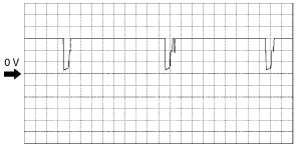
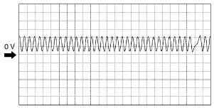
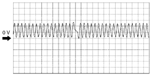
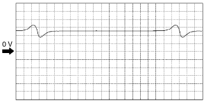
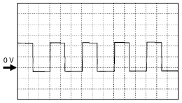
Inspection Using An Oscilloscope (Reference)
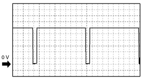
IGT1, IGT2 control signals
am6zzw00008175
|
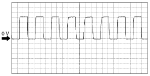
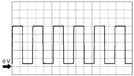
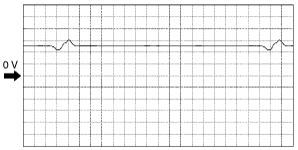
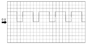
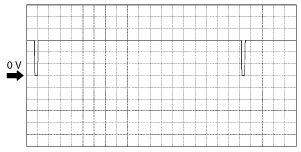
Generator output voltage signal
am6zzw00008176
|
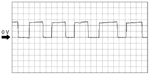
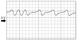
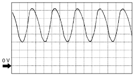
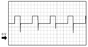
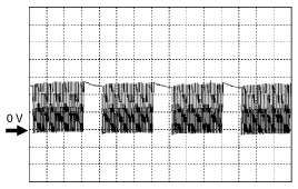
HO2S (front) signal
am6zzw00008177
|
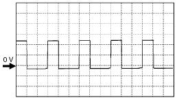
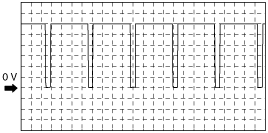
Generator field coil control signal
am6zzw00008178
|
CKP sensor signal
(+)
am6zzw00008179
|
(–)
am6zzw00008180
|
VSS signal
am6zzw00008181
|
CMP sensor signal
L3 engine (+)
am6zzw00008182
|
LF engine (+)
am6zzw00008183
|
L3 engine (–)
am6zzw00008184
|
LF engine (–)
am6zzw00008185
|
Input/turbine speed sensor signal
am6zzw00008186
|
Pressure control solenoid signal
(–)
am6zzw00008187
|
(+)
am6zzw00008188
|
HO2S (front) heater control signal
am6zzw00008189
|
IAC signal
(+)
am6zzw00008190
|
(–)
am6zzw00008191
|
Shift solenoid A control
OCV control signal
am6zzw00008192
|
Purge control signal
am6zzw00008193
|
Fuel injection control
am6zzw00008194
|
Shift solenoid C control
am6zzw00008195
|
Shift solenoid A control
am6zzw00008196
|
Shift solenoid B control
am6zzw00008197
|