EV TRANSAXLE REMOVAL/INSTALLATION [A71M]
id0525a7000700
Special service tool (SST)
|
For Ford manufactured SSTs, the SST numbers are listed as shown below so that it is possible to check both the Mazda and Ford SST numbers.
1. : Mazda SST number
2. : Global SST number
|
|
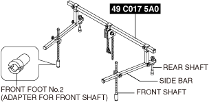
1: 49 C017 5A0
2: –
Engine support set
|
 |
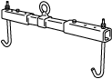
1: 49 UN30 3050
2: 303–050
Engine lifting bracket
|
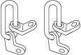 |
1: 49 L017 5A0
2: –
Support hanger
|
 |
-
Caution
-
• During work on this location, there is the risk of accidentally pulling on the front ABS wheel speed sensor wiring harness, causing an open circuit. Before beginning the work, disconnect the front ABS wheel speed sensor and move the front ABS wheel speed sensor out of the way so that the wiring harness does not get pulled accidently.
• If the steering wheel turns while the steering shaft and the steering gear and linkage are disconnected, internal damage to the clock spring may occur. After disconnecting the steering shaft, fasten the steering wheel with tape or a cable so that it does not turn.
-
Warning
-
<<High voltage>>
• If the necessary measures are not taken before servicing an electric vehicle, it could cause electrical shock and result in serious injury or, in the worst case, death. Before servicing the electric vehicle, refer to [HIGH VOLTAGE SERVICE CAUTIONS] in the general information and implement the necessary measures. (See
HIGH VOLTAGE SERVICE CAUTIONS.)
High Voltage Part Inspection And Removal/Installation Notes
-
Warning
-
<<High voltage>>
• If necessary measures such as wearing the correct protective gear are not taken when inspecting or removing/installing the high voltage parts, it could cause electrical shock and result in serious injury or, in the worst case, death.
• Before inspecting or removing/installing the high voltage parts, refer to [HIGH VOLTAGE SERVICE CAUTIONS] in the general information and [High Voltage Part Inspection and Removal/Installation Notes] of the high voltage system service cautions and implement the necessary measures and preparations. (See
HIGH VOLTAGE SERVICE CAUTIONS.) (See
HIGH VOLTAGE SYSTEM SERVICE CAUTIONS.)
1. Verify that the READY indicator on the instrument cluster is not illuminated.
-
• If the READY indicator is lit, switch the main power OFF.
2. Disconnect the negative lead-acid battery terminal. (See NEGATIVE LEAD-ACID BATTERY TERMINAL DISCONNECTION/CONNECTION.)
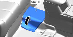
3. Partially peel back the cover.
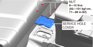
4. Remove the service hole cover.
5. Wear insulating gloves and remove the service plug using the following procedure.
-
Warning
-
<<High voltage>>
• Touching the terminal on the vehicle side can result in serious injury or death from electric shock. For this reason, after removing the service plug, cover the vehicle-side terminals with insulating tape so that they cannot be touched.
• Do not touch high voltage parts for 10 min after removing service plug. Electric charges may be stored on the condenser for 10 min after the service plug is removed, and touching high voltage parts during that time can result in serious injury or death from electric shock.
• Service plugs must be removed by workers inspecting/removing/installing high voltage parts. Keep the removed service plug on your person until inspection/removal/installation of the high voltage parts is completed to prevent other workers from accidentally installing the service plug.
-
Caution
-
<<High voltage>>
• After removing the service plug, cover the vehicle side terminals with insulating tape to prevent foreign matter from adhering to them.
• When you are keeping the service plug on your person, cover the service plug terminals with insulating tape to prevent damage to them.
• Do not switch the main power ON (READY on) after removing the service plug. If the main power is switched ON (READY on) after removing the service plug, the vehicle may malfunction.
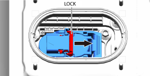
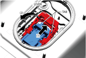
- (1) Slide the lock in the direction of the arrow shown in the figure. (Do not pull out completely)
-
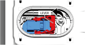
- (2) Raise the lever.
-
- (3) Press the area indicated by arrow (1) shown in the figure, release the tabs, and then raise the lever until it is perpendicular.
-
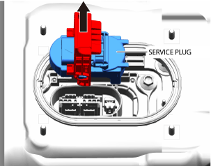
- (4) Hold the lever and pull the service plug straight up.
-
6. After removing the service plug, leave it for 10 min.
7. Wear insulating gloves and measure the voltage at the high voltage cable connection (junction box No.3 side) using the following procedure.
- (1) Remove the seal cover. (See SEAL COVER REMOVAL/INSTALLATION.)
-
-
Caution
-
<<High voltage>>
• Be careful not to allow foreign matter or water droplets to enter the junction box No.3. Since the junction box No.3 has a high voltage circuit, there is a risk of malfunction if foreign matter or water drops enter it.
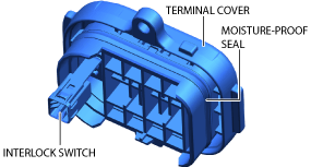
• Remove the terminal cover by pulling it straight up. The terminal cover is fitted with an interlock switch. This interlock switch may be damaged if the terminal cover is removed while being tilted.
• Do not touch the moisture-proof seal on the terminal cover. If the seal is touched or damaged, replace the terminal cover.
- (2) Remove the terminal cover. (See HIGH VOLTAGE CABLE REMOVAL/INSTALLATION.)
-
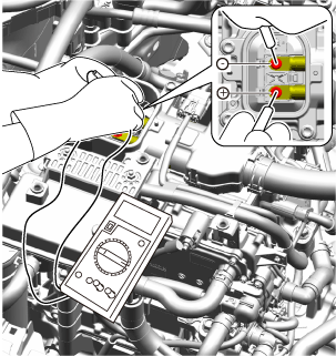
- (3) Measure the voltage at the high voltage cable connection.
-
-
Note
-
• Use a voltmeter with a measurement range of 450 V DC or more.
-
― Verify that the voltmeter indicates 0 V and go to the next step.
• Verify that the waterproof rubber on the terminal cover is securely installed.
• Be careful not to damage the interlock, and install it securely.
- (4) Install the terminal cover. (See HIGH VOLTAGE CABLE REMOVAL/INSTALLATION.)
-
-
Note
-
• Remove/install the EV transaxle without draining the coolant because it is not necessary to replace the coolant.
8. Remove the coolant reserve tank installation nuts and set the coolant reserve tank aside where it does not interfere with the radiator hose and the water hose connected. (See COOLANT RESERVE TANK REMOVAL/INSTALLATION.)
9. Remove the DC-DC converter installation bolts and set the DC-DC converter aside where it does not interfere with the servicing with the water hoses and the wiring harnesses connected. (See DC-DC CONVERTER REMOVAL/INSTALLATION.)
10. Disconnect the high voltage cable and place it out of the way where it will not interfere with work. (See HIGH VOLTAGE CABLE REMOVAL/INSTALLATION.)
11. Remove the junction box No.3 (junction box No.3 side) by lifting it straight up. (See JUNCTION BOX No.3 REMOVAL/INSTALLATION.)
12. Remove the lead-acid battery and lead-acid battery tray. (See LEAD-ACID BATTERY REMOVAL/INSTALLATION.)
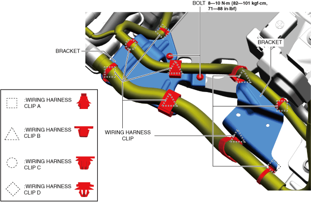
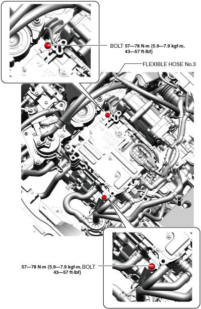
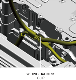
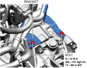
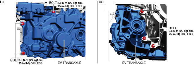
13. Remove the wiring harness clips and bolts as shown in the figure, then remove the brackets.
-
Note
-
• Place the removed wiring harness out of the way where it will not interfere with work.
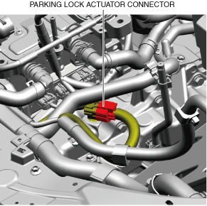
14. Disconnect the parking lock actuator connector.
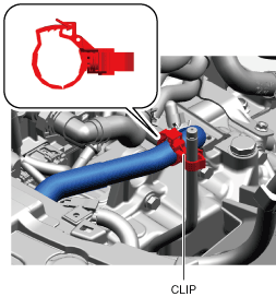
15. Remove the clip shown in the figure.
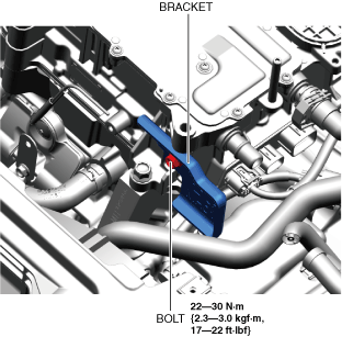
16. Remove the bolt shown in the figure and remove the bracket.
17. Wearing insulating gloves, remove the bolts as shown in the figure.
18. Remove the wheel and tire. (See WHEEL AND TIRE REMOVAL/INSTALLATION.)
19. Disconnect the tie-rod end from the steering knuckle. (See TIE-ROD END REMOVAL/INSTALLATION.)
20. Disconnect the front lower arm ball joint from the steering knuckle. (See FRONT LOWER ARM REMOVAL/INSTALLATION.)
21. Disconnect the front drive shaft (LH) from the EV transaxle. (See FRONT DRIVE SHAFT REMOVAL/INSTALLATION.)
22. Disconnect the front drive shaft (RH) from the EV transaxle. (See FRONT DRIVE SHAFT REMOVAL/INSTALLATION.)
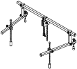
23. Install the SST using the following procedure.
-
Caution
-
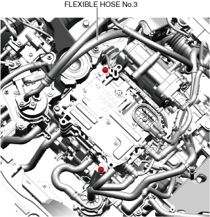
• When installing the SST, there is the risk of contact with flexible hose No.3. Hold flexible hose No.3 out of the way when installing the SST.
-
Note
-
• For the basic operation of the SST, refer to the instruction manual included with the SST.
- (1) Install the SST front foot No.2 onto the left and right front shafts.
-
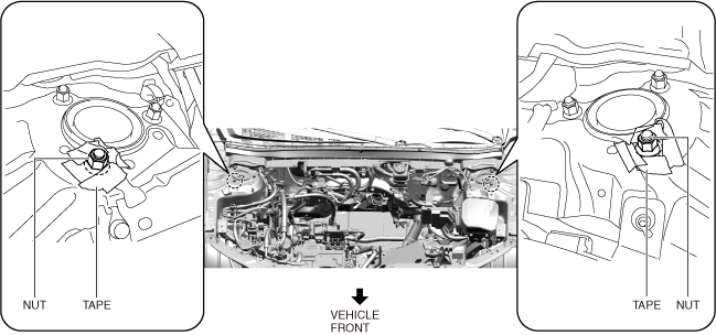
- (2) Protect the position shown in the figure using protective tape.
-
- (3) To allow installation of the SST, disconnect the clips and move the wiring harness to a location where it will not interfere with work.
-
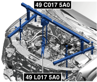
- (4) Wearing insulating gloves, install the SSTs as shown in the figure.
-
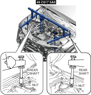
- (5) Set the rear shafts of the SST (49 C017 5A0) on the left/right front shock absorber nuts as shown in the figure (upper side).
-
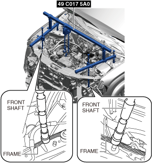
- (6) Set the front shafts of the SST (49 C017 5A0) as shown in the figure.
-
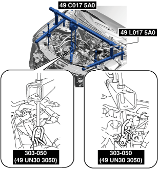
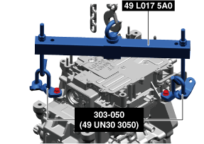
- (7) As shown in the figure, install the SST (49 L017 5A0) onto the SST (49 C017 5A0). (See SST Installation Note)
-
- (8) Install the SST (49 L017 5A0) on to the SSTs (49 UN30 3050) with the SST (49 L017 5A0) hook facing the outside.
-
- (9) Adjust the height of the left and right side bars of the SST so that they are level, then tighten each part of the SST.
-
- (10) Apply tension to the chain to support the inverter and the electric motor, and verify that the inverter and the electric motor are securely hung.
-
24. Remove the front under cover No.2. (See FRONT UNDER COVER No.2 REMOVAL/INSTALLATION.)
25. Remove the front under cover No.1. (See FRONT UNDER COVER No.1 REMOVAL/INSTALLATION.)
26. Remove the front deflector. (See DEFLECTOR REMOVAL/INSTALLATION.)
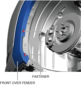
27. Remove the fasteners shown in the figure and slightly bend back the front over fender.
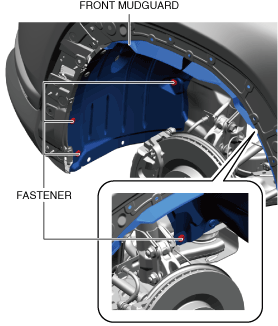
28. Remove the fasteners shown in the figure and slightly bend back the front mudguard.
29. Remove the front splash shield. (See SPLASH SHIELD REMOVAL/INSTALLATION.)
30. Remove the gusset. (See FRONT CROSSMEMBER REMOVAL/INSTALLATION.)
31. Remove floor under cover No.1. (See FLOOR UNDER COVER REMOVAL/INSTALLATION.)
32. Drain the ATF. (See AUTOMATIC TRANSAXLE FLUID (ATF) REPLACEMENT [A71M].)
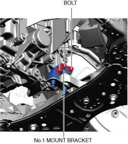
33. Remove the No.1 mount bracket.(See MOUNT DISASSEMBLY/ASSEMBLY.)(See No.1 Mount Installation Note.)
34. Remove the No.1 mount rubber.(See MOUNT DISASSEMBLY/ASSEMBLY.)(See No.1 Mount Installation Note.)
-
Note
-
• Remove/install the EV transaxle without draining the coolant because it is not necessary to replace the coolant.
35. Remove the electric water pump installation bolts and set the electric water pump aside where it does not interfere with the water hoses and the clip connected. (See ELECTRIC WATER PUMP REMOVAL/INSTALLATION.)
36. Remove the support bracket. (See SUPPORT BRACKET REMOVAL/INSTALLATION [A71M].)
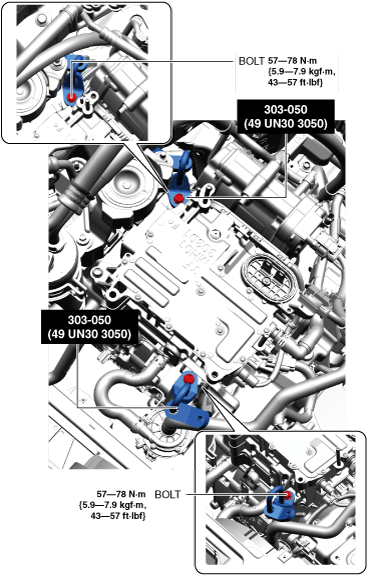
37. Remove the bolts shown in the figure, and set the brackets aside.
-
Caution
-
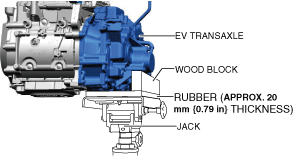
• Be careful that the EV transaxle does not fall off of the transmission jack.
38. Support the EV transaxle on a jack.
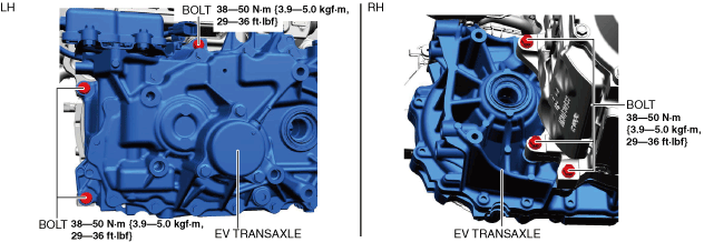
39. Remove the EV transaxle installation bolts. (See EV Transaxle Installation Note.)
40. Remove the EV transaxle.
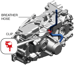
41. Remove the clip as shown in the figure and remove the breather hose.
42. Install in the reverse order of removal.
No.1 Mount Installation Note
1. Temporarily tighten the bolts shown in the figure.
2. Tighten the bolts shown in the figure.
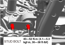
3. Tighten the stud bolts.
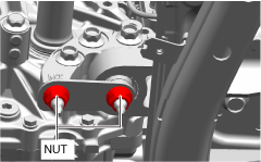
4. Temporarily tighten the nuts shown in the figure.
5. Tighten the nut shown in the figure.
SST Installation Note
1. When installing the SST (49 L017 5A0) to the vehicle, install it as shown in the figure.
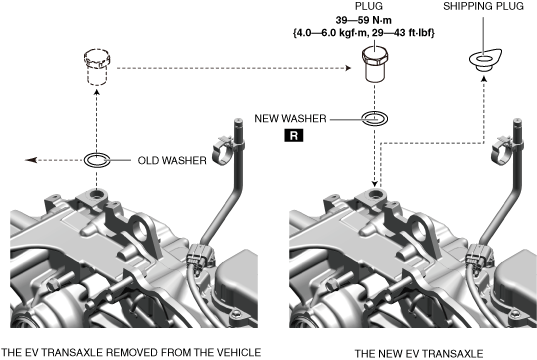
EV Transaxle Installation Note
1. If the EV transaxle is replaced with a new one, perform the following procedure.
- (1) Remove the shipping plug from the new EV transaxle.
-
- (2) Remove the plug from the EV transaxle removed from the vehicle.
-
- (3) Perform the ATF adjustment for the new EV transaxle. (See AUTOMATIC TRANSAXLE FLUID (ATF) ADJUSTMENT [A71M].)
-
- (4) Install the removed plug and a new washer to the new EV transaxle.
-
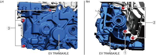
2. Install the EV transaxle, and temporarily tighten the bolts shown in the figure.
3. Tighten the EV transaxle installation bolts in the order shown in the figure.