AIRFLOW MODE MAIN LINK REMOVAL/INSTALLATION
id071100801800
L.H.D.
1. Disconnect the negative battery cable.
2. Detach the bonnet release lever from the lower panel. (See BONNET LATCH AND RELEASE LEVER REMOVAL/INSTALLATION[L.H.D.].) (See BONNET LATCH AND RELEASE LEVER REMOVAL/INSTALLATION[R.H.D.].)
3. Remove the front scuff plate (LH). (See FRONT SCUFF PLATE REMOVAL/INSTALLATION.)
4. Remove the front side trim (LH). (See FRONT SIDE TRIM REMOVAL/INSTALLATION.)
5. Remove the lower panel. (See LOWER PANEL REMOVAL/INSTALLATION.)
6. Remove the shower duct (LH).
7. Remove the airflow mode actuator. (full-auto air conditioner) (See AIRFLOW MODE ACTUATOR REMOVAL/INSTALLATION.)
8. Disconnect the airflow mode wire. (See CLIMATE CONTROL UNIT REMOVAL[MANUAL AIR CONDITIONER].)
9. Remove the airflow mode rod.
10. Remove the airflow mode main link.
11. Install in the reverse order of removal.
12. Adjust the airflow mode wire. (See CLIMATE CONTROL UNIT WIRE ADJUSTMENT.)
R.H.D.
1. Disconnect the negative battery cable.
2. Remove the following parts:
- (1) Front door (See FRONT DOOR REMOVAL/INSTALLATION.)
-
- (2) Front scuff plate (See FRONT SCUFF PLATE REMOVAL/INSTALLATION.)
-
- (3) Front side trim (See FRONT SIDE TRIM REMOVAL/INSTALLATION.)
-
- (4) Decoration panel (See DECORATION PANEL REMOVAL/INSTALLATION.)
-
- (5) Glove compartment (See GLOVE COMPARTMENT REMOVAL/INSTALLATION.)
-
- (6) PJB (See PASSENGER JUNCTION BOX (PJB) REMOVAL/INSTALLATION.)
-
- (7) Car-navigation unit (See CAR-NAVIGATION UNIT REMOVAL/INSTALLATION.)
-
- (8) Side wall (See SIDE WALL REMOVAL/INSTALLATION.)
-
- (9) Ashtray panel
-
- (10) Console (See CONSOLE REMOVAL/INSTALLATION.)
-
- (11) Shift lever component (MTX) (See SHIFT MECHANISM REMOVAL/INSTALLATION[EXCEPT A26M-R].) (See SHIFT MECHANISM REMOVAL/INSTALLATION[A26M-R])
-
- (12) Selector lever component (ATX) (See SELECTOR LEVER COMPONENT REMOVAL/INSTALLATION.)
-
- (13) Center panel unit (See CENTER PANEL UNIT REMOVAL/INSTALLATION.)
-
- (14) Hood release lever from lower panel
-
- (15) Lower panel (See LOWER PANEL REMOVAL/INSTALLATION.)
-
- (16) Shower ducts (LH, RH)
-
- (17) Driver-side air bag module (See DRIVER-SIDE AIR BAG MODULE REMOVAL/INSTALLATION.)
-
- (18) Column cover (See COLUMN COVER REMOVAL/INSTALLATION.)
-
- (19) Meter hood (See METER HOOD REMOVAL/INSTALLATION.)
-
- (20) Instrument cluster (See INSTRUMENT CLUSTER REMOVAL/INSTALLATION.)
-
- (21) Steering shaft (See STEERING WHEEL AND COLUMN REMOVAL/INSTALLATION.)
-
- (22) A-pillar trim (See A-PILLAR TRIM REMOVAL/INSTALLATION.)
-
- (23) Windshield wiper arm and blade (See WINDSHIELD WIPER ARM AND BLADE REMOVAL/INSTALLATION.)
-
- (24) Cowl grille (See COWL GRILLE REMOVAL/INSTALLATION.)
-
- (25) Cowl panel (See COWL PANEL REMOVAL/INSTALLATION.)
-
- (26) Windshield wiper motor (See WINDSHIELD WIPER MOTOR REMOVAL/INSTALLATION.)
-
- (27) Dashboard (See DASHBOARD REMOVAL/INSTALLATION.)
-
3. Remove the airflow mode rod.
4. Remove the airflow mode main rink.
5. Install in the reverse order of removal.
Airflow Mode Main Link Installation Note
-
Caution
-
• Apply only the specified grease to links. Otherwise abnormal noise or improper operation may result.
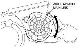
1. Push and hold each airflow mode sub link in the direction of the arrow.
2. Set the airflow mode main link to the A/C unit as shown in the figure.
3. Press the airflow mode main link lightly to the A/C unit it in the direction shown by the arrow, then set the projections of each airflow mode sub link into the grooves of the airflow mode main link.
4. Rotate airflow mode main link and verify that each mode is accessed properly.