|
am6zzw00006241
ENGINE REMOVAL/INSTALLATION [MZR 2.0 DISI]
id011007800400
1. Remove the plug hole plate. (See PLUG HOLE PLATE REMOVAL/INSTALLATION [MZR 2.0 DISI].)
2. Remove the air hose and air cleaner component. (See INTAKE-AIR SYSTEM REMOVAL/INSTALLATION [MZR 2.0 DISI].)
3. Remove the PCM and PCM bracket component. (See PCM REMOVAL/INSTALLATION [MZR 2.0 DISI].)
4. Remove the battery and battery tray. (See BATTERY REMOVAL/INSTALLATION [MZR 2.0 DISI].)
5. Remove the front wheels and tires (See GENERAL PROCEDURES (SUSPENSION).)
6. Remove the aerodynamic under cover No.1 and No.2. (See AERODYNAMIC UNDER COVER NO.1 REMOVAL/INSTALLATION.) (See AERODYNAMIC UNDER COVER NO.2 REMOVAL/INSTALLATION.)
7. Set the front mudguards out of the way. (See FRONT MUDGUARD REMOVAL/INSTALLATION.)
8. Remove the splash shields. (See SPLASH SHIELD REMOVAL/INSTALLATION.)
9. Remove the drive belt. (See DRIVE BELT REMOVAL/INSTALLATION [MZR 2.0 DISI].)
10. Remove the TWC. (See EXHAUST SYSTEM REMOVAL/INSTALLATION [MZR 2.0 DISI].)
11. Drain the engine coolant. (See ENGINE COOLANT REPLACEMENT [MZR 2.0 DISI].)
12. Drain the ATF (ATX) or transaxle oil (MTX). (See AUTOMATIC TRANSAXLE FLUID (ATF) REPLACEMENT [FS5A-EL] (ATX).) (See TRANSAXLE OIL REPLACEMENT [G66M-R] (MTX).)
13. Disconnect the drive shafts from the engine side, set the drive shafts out of the way. (See DRIVE SHAFT REMOVAL/INSTALLATION.)
14. Disconnect the lower radiator hose from the engine side. (See THERMOSTAT REMOVAL/INSTALLATION [MZR 2.0 DISI].)
15. Disconnect the brake vacuum hose from the intake manifold side. (See VACUUM HOSE REMOVAL/INSTALLATION [MZR 1.8, MZR 2.0, MZR 2.0 DISI, MZR 2.5].)
16. Disconnect the evaporative hose from the purge solenoid valve. (See PURGE SOLENOID VALVE REMOVAL/INSTALLATION [MZR 2.0 DISI].)
17. Disconnect the upper radiator hose and water hose from the engine side. (See COOLING FAN MOTOR REMOVAL/INSTALLATION [MZR 2.0 DISI].)
18. Disconnect the heater hoses. (See A/C UNIT REMOVAL/INSTALLATION.)
19. Disconnect the fuel hose. (See QUICK RELEASE CONNECTOR REMOVAL/INSTALLATION [MZR 2.0 DISI].)
20. Disconnect the ATF oil hose, selector cable, and wiring harness. (ATX) (See AUTOMATIC TRANSAXLE REMOVAL/INSTALLATION [FS5A-EL].)
21. Disconnect the shift cable. (MTX) (See MANUAL TRANSAXLE REMOVAL/INSTALLATION [G66M-R] (MTX).)
22. Remove the clutch release cylinder with the pipe still connected. (MTX) (See CLUTCH RELEASE CYLINDER REMOVAL/INSTALLATION [G66M-R].)
23. Set the cooler hose (LO) out of the way. (See REFRIGERANT LINE REMOVAL/INSTALLATION.)
24. Remove the A/C compressor with the pipes still connected. (See A/C COMPRESSOR REMOVAL/INSTALLATION.)
25. Remove the wiring harness installation bolt and nuts shown in the figure.
am6zzw00006241
|
26. Disconnect the connectors and wiring harnesses related to the engine removal/installation.
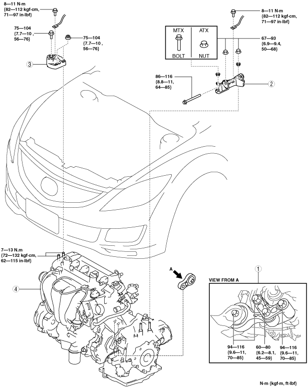
27. Remove in the order indicated in the table.
28. Install in the reverse order of removal.
29. Start the engine. And inspect and adjust the following:
am6zzw00006294
|
|
1
|
No.1 engine mount
|
|
2
|
No.4 Engine mount bracket
|
|
3
|
No.3 Engine mount bracket
|
|
4
|
Engine, transaxle
|
No.1 Engine Mount Removal Note
No.3 Engine Mount Bracket, No.4 Engine Bracket Removal Note
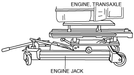
1. Secure the engine and transaxle using an engine jack.
am6zzw00001215
|
Engine Mount Installation Note
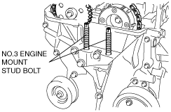
1. Tighten the No. 3 engine mount stud bolts.
am6zzw00001967
|
2. Secure the engine and transaxle using an engine jack.
am6zzw00001215
|
3. Temporarily tighten the No.3 engine mount bracket installation bolt and nuts.
am6zzw00006242
|
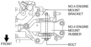
4. Align the No.4 engine mount bracket installation hole to the No.4 engine mount rubber on the body and temporarily tighten the bolt shown in the figure.
am6zzw00006852
|
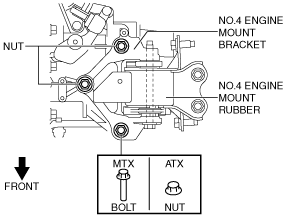
5. Temporarily tighten the No.4 engine mount bracket installation bolt and nuts.
am6zzw00006243
|
6. Install the No.1 engine mount rubber and front crossmember as a single unit. (See FRONT CROSSMEMBER REMOVAL/INSTALLATION.)
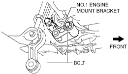
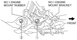
7. Tighten the No.1 engine mount bracket installation bolts.
am6zzw00006272
|
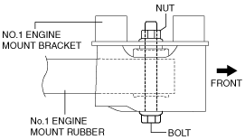
8. Temporarily tighten the No.1 engine mount rubber installation bolts.
am6zzw00006853
|
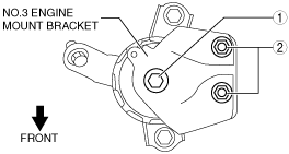
9. Tighten the No.3 engine mount bracket installation bolt and nuts in the order shown in the figure.
am6zzw00006246
|
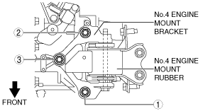
10. Tighten the No.4 engine mount bracket installation bolts and nuts in the order shown in the figure.
am6zzw00006296
|
11. Tighten the bolt shown in the figure.
am6zzw00006852
|
12. Tighten the No.1 engine mount rubber installation bolts in the order shown in the figure.
am6zzw00006297
|
|
No. |
Tightening torque |
|---|---|
|
1
|
60—80 N·m {6.2—8.1 kgf·m, 45—59 ft·lbf}
|
|
2
|
94—116 N·m {9.6—11 kgf·m, 70—85 ft·lbf}
|