AUTOMATIC TRANSAXLE REMOVAL/INSTALLATION [FS5A-EL]
id051721802400
-
Caution
-
• Secure the steering wheel using tape or a cable to prevent the steering shaft from rotating after disconnecting the steering shaft. If the steering wheel rotates after the steering shaft and the steering gear and linkage are disconnected, the internal parts of the clock spring could be damaged.
• Water or foreign objects entering the connector can cause a poor connection or corrosion. Be sure not to drop water or foreign objects on the connector when disconnecting it.
1. Disconnect the negative battery cable.
2. Remove the aerodynamic under cover NO. 1 and NO. 2. (See AERODYNAMIC UNDER COVER NO.1 REMOVAL/INSTALLATION.) (See AERODYNAMIC UNDER COVER NO.2 REMOVAL/INSTALLATION.)
3. Drain the ATF into a separate suitable container. (See AUTOMATIC TRANSAXLE FLUID (ATF) REPLACEMENT [FS5A-EL].)
4. Disconnect and/or remove the following parts in the engine compartment.
- (1) Remove the battery and battery tray. (See BATTERY REMOVAL/INSTALLATION [MZR 1.8, MZR 2.0, MZR 2.5].) (See BATTERY REMOVAL/INSTALLATION [MZR 2.0 DISI].)
- (2) Disconnect the EPS control module connectors from the EPS control module.
-
- (3) Remove the air cleaner assembly. (See INTAKE-AIR SYSTEM REMOVAL/INSTALLATION [MZR 1.8, MZR 2.0, MZR 2.5].) (See INTAKE-AIR SYSTEM REMOVAL/INSTALLATION [MZR 2.0 DISI].)
- (4) Disconnect the selector cable from transaxle.
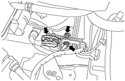
- (5) Disconnect the connector and GND wiring harness from transaxle.
- (6) Remove the bracket from transaxle.
- (7) Disconnect the oil hose from transaxle.
- (8) Remove the starter. (See STARTER REMOVAL/INSTALLATION [MZR 1.8, MZR 2.0, MZR 2.5].) (See STARTER REMOVAL/INSTALLATION [MZR 2.0 DISI].)
5. Disconnect and/or remove the following parts related to the suspension and axle.
- (1) Remove the front tires. (See GENERAL PROCEDURES (FRONT AND REAR AXLES).)
- (2) Set the front mudguard out of the way. (See FRONT MUDGUARD REMOVAL/INSTALLATION.)
- (3) Remove the splash shield. (See SPLASH SHIELD REMOVAL/INSTALLATION.)
- (4) Disconnect the ABS wheel-speed sensors from steering knuckles. (See FRONT ABS WHEEL-SPEED SENSOR REMOVAL/INSTALLATION.)
- (5) Disconnect the brake hose bracket from shock absorbers. (See BRAKE HOSE (FRONT) REMOVAL/INSTALLATION.)
- (6) Disconnect the tie-rod end from steering knuckles. (See FRONT CROSSMEMBER REMOVAL/INSTALLATION.)
- (7) Disconnect the front lower arm from steering knuckles. (See FRONT LOWER ARM REMOVAL/INSTALLATION.)
- (8) Disconnect the front stabilizer control links from front shock absorbers. (See FRONT SHOCK ABSORBER AND COIL SPRING REMOVAL/INSTALLATION.)
6. Disconnect and/or remove the following parts for the underbody.
- (1) Remove the tunnel member. (See EXHAUST SYSTEM REMOVAL/INSTALLATION [MZR 1.8, MZR 2.0, MZR 2.5].) (See EXHAUST SYSTEM REMOVAL/INSTALLATION [MZR 2.0 DISI].)
- (2) Center floor under cover (left side) (vehicles with center floor under cover) (See FLOOR UNDER COVER REMOVAL/INSTALLATION.)
- (3) Disconnect the A/F sensor and HO2S connector. (See AIR FUEL RATIO (A/F) SENSOR REMOVAL/INSTALLATION [MZR 1.8, MZR 2.0, MZR 2.5].) (See AIR FUEL RATIO (A/F) SENSOR REMOVAL/INSTALLATION [MZR 2.0 DISI].)
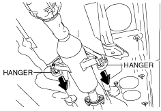
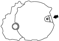
- (4) Remove the hanger on the TWC side as shown in the figure and set the hanger aside.
-
- (5) Remove the steering shaft cover. (See STEERING WHEEL AND COLUMN REMOVAL/INSTALLATION [WITH ADVANCED KEYLESS ENTRY AND PUSH BUTTON START SYSTEM].) (See STEERING WHEEL AND COLUMN REMOVAL/INSTALLATION [WITHOUT ADVANCED KEYLESS ENTRY AND PUSH BUTTON START SYSTEM].)
- (6) Disconnect the steering shaft from the steering gear and linkage. (See STEERING WHEEL AND COLUMN REMOVAL/INSTALLATION [WITH ADVANCED KEYLESS ENTRY AND PUSH BUTTON START SYSTEM].) (See STEERING WHEEL AND COLUMN REMOVAL/INSTALLATION [WITHOUT ADVANCED KEYLESS ENTRY AND PUSH BUTTON START SYSTEM].)
- (7) Remove the steering dust cover. (See STEERING WHEEL AND COLUMN REMOVAL/INSTALLATION [WITH ADVANCED KEYLESS ENTRY AND PUSH BUTTON START SYSTEM].) (See STEERING WHEEL AND COLUMN REMOVAL/INSTALLATION [WITHOUT ADVANCED KEYLESS ENTRY AND PUSH BUTTON START SYSTEM].)
- (8) Remove the transverse member. (See TRANSVERSE MEMBER REMOVAL/INSTALLATION.)
- (9) Remove the front auto leveling sensor. (Vehicle with discharge headlight system) (See AUTO LEVELING SENSOR REMOVAL/INSTALLATION.)
-
Caution
-
• Refer to the SST instruction manual for the basic handing procedure.
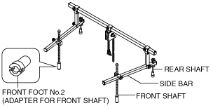
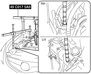
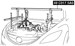
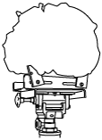
7. Install the SST using the following procedure.
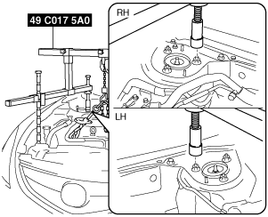
- (1) As shown in the figure, set the rear shafts of the SST to the left and right shock absorber nuts.
-
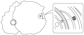
- (2) Install front foot No.2 to the left/right front shaft of the SST, then align the groove of the front shaft of the SST with the folded up part of the vehicle as shown in the figure.
-
- (3) Adjust the positions of the SST side bars so that they are the same height (left and right) and horizontal. Make sure each joint is securely tightened.
-
-
Warning
-
• Improperly jacking a transaxle is dangerous. It can slip off the jack and may cause serious injury.
-
Caution
-
• To prevent the torque converter and transaxle from separating, remove the transaxle without tilting it toward the torque converter.
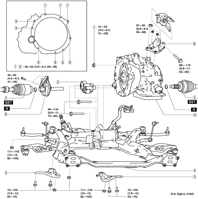
8. Remove in the order shown in the figure.
9. Install in the reverse order of removal.
10. Add the ATF. (SeeAUTOMATIC TRANSAXLE FLUID (ATF) REPLACEMENT [FS5A-EL].)
11. Perform the following test according to the service item. (See MECHANICAL SYSTEM TEST [FS5A-EL].) (See ROAD TEST [FS5A-EL].)
|
Service item
|
Test item
|
|
Line pressure test
|
Stall test
|
Time lag test
|
Road test
|
|
ATX replacement
|
×
|
|
|
|
|
ATX overhaul
|
×
|
×
|
×
|
×
|
|
Torque converter replacement
|
×
|
×
|
|
|
|
Oil pump replacement
|
×
|
|
|
|
|
Clutch system replacement
|
×
|
|
×
|
×
|
× :Test to be performed after the service work
L.H.D.
R.H.D.
|
1
|
Torque converter nuts
|
|
2
|
No.1 engine mount
|
|
3
|
Front crossmember bracket
|
|
4
|
Front crossmember
|
|
5
|
Drive shaft
|
|
6
|
Joint shaft
|
|
7
|
Transaxle mounting bolts (upper side)
|
|
8
|
No.4 engine mount bracket
|
|
9
|
Transaxle mounting bolts (lower side)
|
|
10
|
Transaxle
|
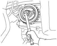
Torque Converter Installation Nuts Removal Note
1. Hold the crankshaft pulley to prevent drive plate from rotating.
2. Remove the torque converter nuts from the starter installation hole.
Transaxle Removal Note
1. Adjust the SST (49 C017 5A0) and lean the engine toward the transaxle.
2. Support the transaxle on a jack.
3. Remove the transaxle mounting bolts.
4. Remove the transaxle.
Transaxle Installation Note
-
Caution
-
• Verify that the torque converter stud bolts are inserted into the drive plate bolt holes, and install the transaxle installation bolts. Otherwise, the drive plate could be damaged.
1. Verify that the torque converter stud bolts are inserted into the drive plate bolt holes from the starter installation hole.
2. Install the transaxle mounting bolts.
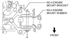
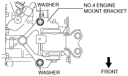
No.4 Engine Mount Installation Note
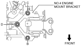
1. Align the No.4 engine mount bracket installation hole to the No.4 engine mount rubber on the body and temporarily tighten bolt A.
2. Install the washers in the positions shown in the figure.
3. Temporarily tighten nuts B, C and D.
4. Tighten nut B, and then the nuts in the order of C, D.
-
Tightening torque
-
67—93 N·m {6.9—9.4 kgf·m, 50—68 ft·lbf}
5. Tighten the bolt A.
-
Tightening torque
-
86—116 N·m {8.8—11 kgf·m, 64—85 ft·lbf}
No.1 Engine Mount Installation Note
1. Tighten bolts on the No.1 engine mount in the order of A→B→C.
-
Tightening torque
-
94—116 N·m {9.6—11 kgf·m, 70—85 ft·lbf}
Torque Converter Installation Nuts Installation Note
1. Hold the crankshaft pulley to prevent drive plate from rotating.
-
Caution
-
• Loosely and equally tighten the torque converter nuts, then further tighten them to the specified tightening torque.
2. Tighten the torque converter nuts from the starter installation hole.
-
Tightening torque
-
41—54 N·m {4.2—5.5 kgf·m, 31—39 ft·lbf}