Caution
• When marking using tape, perform the procedure so as not to soil the headliner.
ac8wzw00004126
|
ANTENNA FEEDER NO.2 REMOVAL/INSTALLATION
id092000812300
Replacement part
|
Inner liftgate grommet
Quantity: 4
Location of use: Liftgate and roof panel
|
1. Refer to the headliner removal/installation and perform the preparation before servicing. (See HEADLINER REMOVAL/INSTALLATION.)
2. Disconnect the negative battery terminal. (See NEGATIVE BATTERY TERMINAL DISCONNECTION/CONNECTION.)
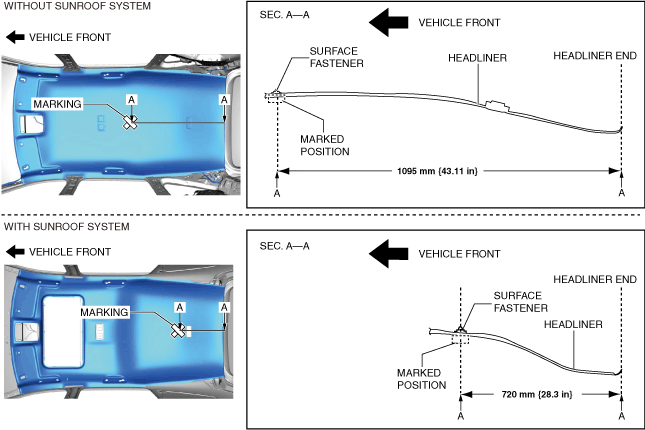
3. Mark the position shown in the figure using tape to verify the position of the surface fastener.
ac8wzw00004126
|
4. Remove the following parts:
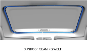
5. Remove the sunroof seaming welt. (with sunroof system)
ac8wzw00004057
|
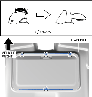
6. Remove the hooks in the direction of arrow shown in the figure. (with sunroof system)
ac8wzw00004058
|
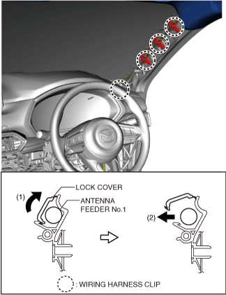
7. Open the lock covers of the wiring harness clips in the direction of arrow (1) shown in the figure and remove the antenna feeder No.1 in the direction of arrow (2).
ac8wzw00001868
|
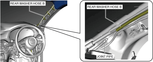
8. Disconnect rear washer hose B from the joint pipe.
ac8wzw00001869
|
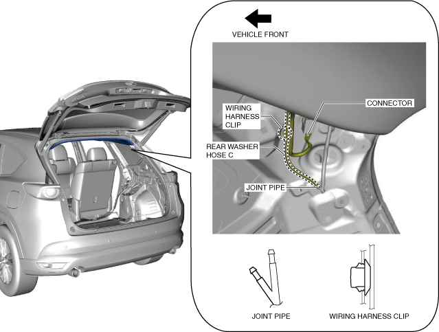
9. Disconnect rear washer hose C from the joint pipe.
ac8wzw00003126
|
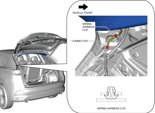
10. Remove the wiring harness clips.
11. Disconnect the connector.
12. Remove the wiring harness clip.
ac8wzw00001871
|
13. Disconnect the connector.
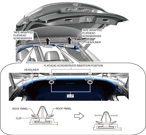
14. Insert a tape-wrapped flathead screwdriver into the position shown in the figure, move it in the direction of the arrow, and then detach the clips.
ac8wzw00001872
|
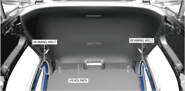
15. Temporarily install the seaming welts shown in the figure to the headliner.
ac8wzw00001873
|
16. Refer to the headliner removal/installation and remove the surface fastener from the roof panel. (See HEADLINER REMOVAL/INSTALLATION.)
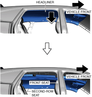
17. Move the headliner in the direction of arrows shown in the figure and set it on front seats and second-row seats.
ac8wzw00001876
|
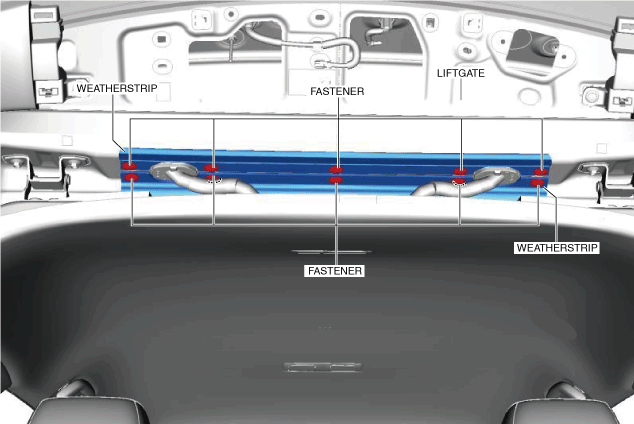
18. Remove the fasteners.
ac8wzw00001877
|
19. Remove the weatherstrips.
20. Disconnect the connectors.
ac8wzw00003492
|
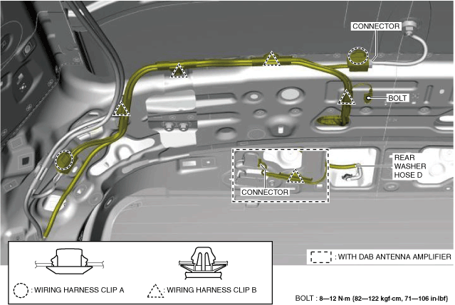
21. Remove the bolt.
22. Remove wiring harness clips A and B.
23. Disconnect rear washer hose D.
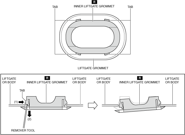
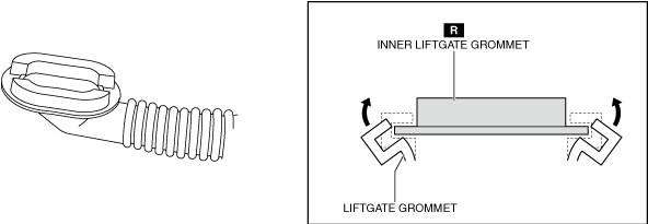
24. Partially peel the liftgate grommets in the direction of the arrows shown in the figures, and remove the liftgate grommets from the inner liftgate grommets.
ac8wzw00001879
|
25. While pressing the inner liftgate grommet tab in the order of arrows (1) and (2) using the remover tool, remove each inner liftgate grommet from the liftgate and the body. (See Liftgate Grommet Installation Note.)
ac8wzw00001880
|
26. Remove antenna feeder No.2.
27. Install in the reverse order of removal.
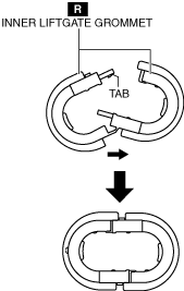
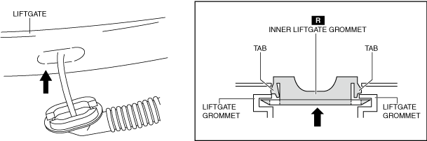
Liftgate Grommet Installation Note
1. Install the liftgate grommet using the following procedure.
ac8wzw00001881
|
ac8wzw00001882
|
ac8wzw00001883
|