FLOOR COVERING REMOVAL/INSTALLATION [(E)]
id0917000522x2
Front Floor Covering
-
Warning
-
1. Remove the front seat installation bolts. (With power seat) (See FRONT SEAT REMOVAL/INSTALLATION [(E)].)
2. Remove the select lever knob. (See SELECTOR LEVER REMOVAL/INSTALLATION [A71M].)
3. Switch the main power OFF.
4. Disconnect the negative lead-acid battery terminal and wait for 1 min or more. (See NEGATIVE LEAD-ACID BATTERY TERMINAL DISCONNECTION/CONNECTION.)
5. Perform the following procedure 2 times to allow the backup power supply to deplete its stored power.
-
Note
-
• While the power stored in the backup power supply is being depleted, the front door latch and lock actuator does not operate. This does not indicate an improper procedure. Continue to perform the procedure.
• After performing Step (3) and the front door latch and lock actuator starts to operate, the door lock switch (driver's side) no longer needs to be operated.
- (1) Close the front door (driver's side).
-
- (2) Open the front door (driver's side).
-
- (3) Within 30 s after performing Step (2), press and hold the unlock side of the door lock switch (driver's side) for 5 s or more.
-
- (4) Wait until the front door latch and lock actuator stops.
-
6. Remove the following parts:
- (1) Joint cover (See STEERING WHEEL AND COLUMN REMOVAL/INSTALLATION.)
-
- (2) Accelerator pedal (See ACCELERATOR PEDAL REMOVAL/INSTALLATION.)
-
- (3) Front seat (See FRONT SEAT REMOVAL/INSTALLATION [(E)].)
-
- (4) Scuff plate (See SCUFF PLATE REMOVAL/INSTALLATION.)
-
- (5) Front side trim (See FRONT SIDE TRIM REMOVAL/INSTALLATION.)
-
- (6) Shift panel (See SHIFT PANEL REMOVAL/INSTALLATION.)
-
- (7) Console panel (See CONSOLE PANEL REMOVAL/INSTALLATION.)
-
- (8) Rear console (See REAR CONSOLE REMOVAL/INSTALLATION.)
-
- (9) Console bracket (See CONSOLE BRACKET REMOVAL/INSTALLATION.)
-
- (10) Front console upper panel (See FRONT CONSOLE UPPER PANEL REMOVAL/INSTALLATION.)
-
- (11) Console side panel (See CONSOLE SIDE PANEL REMOVAL/INSTALLATION.)
-
- (12) Front console box (See FRONT CONSOLE BOX REMOVAL/INSTALLATION.)
-
- (13) Side wall (See SIDE WALL REMOVAL/INSTALLATION.)
-
- (14) Front console (See FRONT CONSOLE REMOVAL/INSTALLATION.)
-
- (15) SAS control module (See SAS CONTROL MODULE REMOVAL/INSTALLATION [TWO-STEP DEPLOYMENT CONTROL SYSTEM (E)].)
-
- (16) Backup power supply component (See BACKUP POWER SUPPLY REMOVAL/INSTALLATION [(E)].)
-
- (17) Audio amplifier (See AUDIO AMPLIFIER REMOVAL/INSTALLATION [(E)].)
-
- (18) Rear heat duct No.1 (See REAR HEAT DUCT REMOVAL/INSTALLATION.)
-
- (19) Dashboard bracket (See DASHBOARD REMOVAL [(E)].) (See DASHBOARD INSTALLATION [(E)].)
-
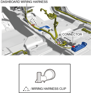
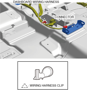
7. Disconnect the connector and remove the wiring harness clips.
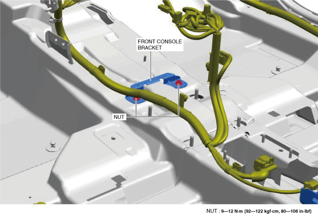
8. Remove the nuts.
9. Remove the front console bracket.
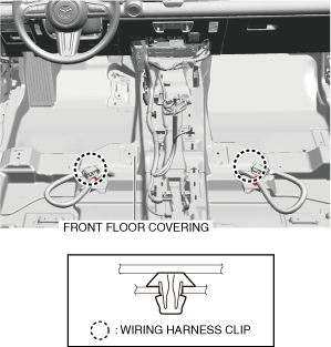
10. Remove the wiring harness clips.
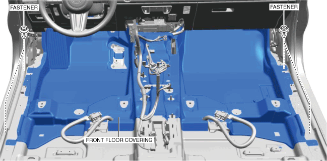
11. Remove the fasteners.
12. Remove the front floor covering from the door opening.
13. Install in the reverse order of removal. (See Front Floor Covering Installation Note.)
Rear Floor Covering
1. Remove the front seat installation bolts. (With power seat) (See FRONT SEAT REMOVAL/INSTALLATION [(E)].)
2. Remove the select lever knob. (See SELECTOR LEVER REMOVAL/INSTALLATION [A71M].)
3. Disconnect the negative lead-acid battery terminal. (See NEGATIVE LEAD-ACID BATTERY TERMINAL DISCONNECTION/CONNECTION.)
4. Remove the following parts:
- (1) Scuff plate (See SCUFF PLATE REMOVAL/INSTALLATION.)
-
- (2) Front seat (See FRONT SEAT REMOVAL/INSTALLATION [(E)].)
-
- (3) Shift panel (See SHIFT PANEL REMOVAL/INSTALLATION.)
-
- (4) Console panel (See CONSOLE PANEL REMOVAL/INSTALLATION.)
-
- (5) Rear console (See REAR CONSOLE REMOVAL/INSTALLATION.)
-
- (6) Backup power supply component (See BACKUP POWER SUPPLY REMOVAL/INSTALLATION [(E)].)
-
- (7) Audio amplifier (See AUDIO AMPLIFIER REMOVAL/INSTALLATION [(E)].)
-
- (8) Rear seat cushion (See REAR SEAT CUSHION REMOVAL/INSTALLATION.)
-
5. Disconnect the connector and remove the wiring harness clip.
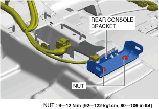
6. Remove the nuts.
7. Remove the rear console bracket.
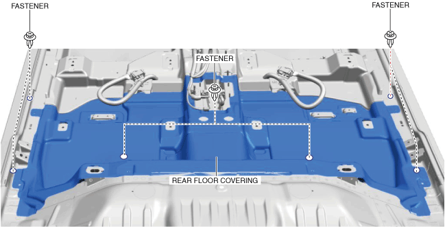
8. Remove the fasteners.
9. Remove the rear floor covering from the door opening.
10. Install in the reverse order of removal.
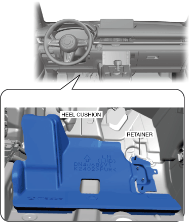
Front Floor Covering Installation Note
1. Before assembling the floor covering, verify that the heel cushion does not interfere with the retainer.