-
― Align the marking on the water pipe with the marking on the water hose.
 a30zzw00004195
-
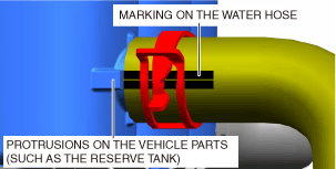
― Align the protrusions on the vehicle parts (such as the reserve tank) with the markings on the water hose.
 a30zzw00004196
COOLING SYSTEM PIPE REMOVAL/INSTALLATION
id301200001700
High Voltage Part Inspection And Removal/Installation Notes
a30zzw00004195
|
a30zzw00004196
|
Coolant draining procedure
Cooling System Pipe Removal
1. Remove using the procedure shown in the figure.
Motor compartment side
a30zzw00007317
|
|
1
|
Upper radiator hose
|
|
|
2
|
Lower radiator hose
|
|
|
3
|
Water hose (coolant reserve tank to DC-DC converter)
|
|
|
4
|
Water hose (electric water pump side to electric motor)
|
|
|
5
|
Water hose (DC-DC converter to inverter)
|
|
|
6
|
Water hose (inverter to water pipe (on reduction gear))
|
|
|
7
|
Water hose (water pipe (on reduction gear) to electric water pump)
|
|
|
8
|
Water pipe (on reduction gear)
|
(See Water pipe (floor) removal.)
|
|
9
|
Water hose (water pipe (on reduction gear) to water pipe (on front crossmember))
|
|
|
10
|
Water hose (water pipe (on front crossmember) to water pipe (on reduction gear))
|
|
|
11
|
Water pipe (on front crossmember)
|
|
|
12
|
Water hose (water pipe (on front crossmember) to water pipe (floor))
|
|
|
13
|
Water hose (water pipe (floor) to water pipe (on front crossmember))
|
On board charger side
a30zzw00007318
|
|
1
|
Water hose (rear)
|
(See Water pipe (floor) removal.)
|
|
2
|
Water pipe (floor)
|
Water pipe (floor) removal
Replacement parts
|
Quick release connector
Quantity: 1
Location of use: Water pipe and water hose connection
|
1. Verify that the READY indicator on the instrument cluster is not illuminated.
2. Disconnect the negative lead-acid battery terminal. (See NEGATIVE LEAD-ACID BATTERY TERMINAL DISCONNECTION/CONNECTION.)
3. Partially peel back the cover.
a30zzw00004019
|
4. Remove the service hole cover.
a30zzw00004020
|
5. Wear insulating gloves and remove the service plug using the following procedure.
a30zzw00004021
|
a30zzw00004502
|
a30zzw00004503
|
a30zzw00007319
|
6. After removing the service plug, leave it for 10 min.
7. Wear insulating gloves and measure the voltage at the high voltage cable connection (junction box No.3 side) using the following procedure.
a30zzw00004024
|
a30zzw00006970
|
a30zzw00004025
|
8. Load the vehicle on the auto lift and lift it up.
9. Remove front under cover No.2. (See FRONT UNDER COVER No.2 REMOVAL/INSTALLATION.)
10. Remove the rear wheel and tire (RH). (See WHEEL AND TIRE REMOVAL/INSTALLATION.)
11. Remove the rear mudguard (RH). (See MUDGUARD REMOVAL/INSTALLATION.)
12. Fold the rear seat backs (RH/LH).
13. Remove the rear package tray. (See REAR PACKAGE TRAY REMOVAL/INSTALLATION.)
14. Remove the trunk mat. (See TRUNK COVERING REMOVAL/INSTALLATION.)
15. Remove the trunk board. (See TRUNK BOARD REMOVAL/INSTALLATION.)
16. Implement the [Coolant Draining Procedure] for the onboard charger removal/installation. (See ONBOARD CHARGER REMOVAL/INSTALLATION.)
17. Remove the onboard charger water hoses (IN side/OUT side).
a30zzw00007320
|
18. Collect the refrigerant. (See REFRIGERANT RECOVERY.)
19. Remove the gusset. (See FRONT CROSSMEMBER REMOVAL/INSTALLATION.)
20. Remove floor under cover. (See FLOOR UNDER COVER REMOVAL/INSTALLATION.)
21. Remove the shield.
a30zzw00007321
|
22. Disconnect the cooler pipe (high voltage battery side). (See REAR COOLER PIPE REMOVAL/INSTALLATION.)
23. Remove the high voltage battery. (See HIGH VOLTAGE BATTERY REMOVAL/INSTALLATION.)
24. Set a tray (volume: approx. 2 L) under the quick release connector at the front part of the water pipe to receive coolant.
25. Slowly remove the quick release connector at the front part of the water pipe and drain the coolant. (See Quick Release Connector Removal.)
26. Remove the water hose (rear).
27. Remove the water pipe (floor).
Water pipe (floor) installation
1. Install the water pipe (floor).
2. Install the water hose (rear).
3. Install the quick release connector. (See Quick Release Connector Installation.)
4. Press and pull the quick release connector forward/back several times and verify that it is connected securely.
5. Install the high voltage battery. (See HIGH VOLTAGE BATTERY REMOVAL/INSTALLATION.)
6. Connect the cooler pipe (high voltage battery side). (See REAR COOLER PIPE REMOVAL/INSTALLATION.)
7. Install the shield.
a30zzw00007321
|
8. Install the onboard charger water hoses (IN side/OUT side).
a30zzw00007320
|
9. Move the rear seat backs (RH/LH) to their upright positions.
10. Wear insulating gloves and install the service plug using the following procedure.
a30zzw00004026
|
a30zzw00004027
|
a30zzw00004028
|
11. Install the service hole cover.
a30zzw00004020
|
12. Close the cover.
a30zzw00004029
|
13. Connect the negative lead-acid battery terminal. (See NEGATIVE LEAD-ACID BATTERY TERMINAL DISCONNECTION/CONNECTION.)
14. Implement the [Coolant Replenishment Procedure] for the onboard charger removal/installation. (See ONBOARD CHARGER REMOVAL/INSTALLATION.)
15. Implement the [Air Bleeding Procedure] for the onboard charger removal/installation. (See ONBOARD CHARGER REMOVAL/INSTALLATION.)
16. Inspect to confirm that there is no coolant leakage at any part. (See COOLANT LEAKAGE INSPECTION.)
17. Install the trunk board. (See TRUNK BOARD REMOVAL/INSTALLATION.)
18. Install the trunk mat. (See TRUNK COVERING REMOVAL/INSTALLATION.)
19. Install the rear package tray. (See REAR PACKAGE TRAY REMOVAL/INSTALLATION.)
20. Install the rear mudguard (RH). (See MUDGUARD REMOVAL/INSTALLATION.)
21. Install the rear wheel and tire (RH). (See WHEEL AND TIRE REMOVAL/INSTALLATION.)
22. Install the front under cover No.2. (See FRONT UNDER COVER No.2 REMOVAL/INSTALLATION.)
23. Lower the vehicle to the ground and adjust the coolant amount to the F line on the coolant reserve tank.
24. Charge the refrigerant. (See REFRIGERANT CHARGING.)
25. Perform the air-conditioning system performance test. (See REFRIGERANT SYSTEM PERFORMANCE TEST.)
26. Install the seal cover. (See SEAL COVER REMOVAL/INSTALLATION.)
Quick Release Connector Removal
1. Remove the quick release connector using the following procedure.
a30zzw00004186
|
Quick Release Connector Installation
1. Inspect the sealing surface of the inverter and water pipe for damage or deformation.
2. Install the quick release connector in the order shown in the figure.
a30zzw00004187
|
3. Install the quick release connector in the order shown in the figure.