 |
am3uuw00003018
ENGINE CONTROL SYSTEM OPERATION INSPECTION [MZR 1.8, MZR 2.0, MZR 2.5]
id0103d4803700
Input Signal System Inspection Procedure
1. Find an irregular signal. (See Finding irregular signals.)
2. Locate source. (See Locating the source of unusual signals.)
3. Repair or replace the malfunctioning part.
4. Confirm that the irregular signal is no longer detected.
Finding irregular signals
1. Start the engine and idle the vehicle. You can assume that any signals that are out of specification by a wide margin are irregular.
2. When recreating the problem, any sudden change in monitor input signals that is not intentionally created by the driver can be determined as irregular.
Locating the source of unusual signals
Thermistor type (IAT sensor and ECT sensor)
am3uuw00003018
|
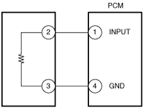
Input signal system inspection for thermistor type
1. When an irregular signal is detected, measure the #1 PCM terminal voltage.
2. Measure the #2 sensor terminal voltage.
GND system inspection for thermistor type
Main Relay Operation Inspection
1. Verify that the main relay clicks when the ignition is switched to ON and off.
Intake Manifold Vacuum Inspection
1. Verify air intake hoses are installed properly.
2. Start the engine and run it at idle.
3. Disconnect the vacuum hose between the intake manifold and purge solenoid valve from the intake manifold side.
4. Connect a vacuum gauge to the intake manifold and measure the intake manifold vacuum.
Electronic Throttle Control System Inspection
Engine coolant temperature compensation inspection
1. Connect the M-MDS to the DLC-2.
2. Access the following PIDs: (See ON-BOARD DIAGNOSTIC TEST [MZR 1.8, MZR 2.0, MZR 2.5].)
3. Verify that the engine is cold, then start the engine.
4. Verify that the engine speed decreases as the engine warms up.
Load compensation inspection
1. Start the engine and idle it.
2. Connect the M-MDS to the DLC-2.
3. Verify that P0506:00 or P0507:00 is not displayed.
4. Access the RPM PID. (See ON-BOARD DIAGNOSTIC TEST [MZR 1.8, MZR 2.0, MZR 2.5].)
5. Verify that the engine speed is within the specification under each load condition.
Throttle position (TP) sweep inspection
1. Connect the M-MDS to the DLC-2.
2. Switch the ignition to ON.
3. Verify that none of the following DTC are displayed:
4. Access the TP_REL PID.
5. Verify that the PID reading is within the TP_REL value. (See PCM INSPECTION [MZR 1.8, MZR 2.0, MZR 2.5].)
6. Gradually depress the throttle pedal and verify that the PID reading increases accordingly.
7. Fully depress the throttle pedal and verify that the PID reading is within WOT value. (See PCM INSPECTION [MZR 1.8, MZR 2.0, MZR 2.5].)
Brake override system operation inspection (GH1***-429761,GH1***-442043,GH10**-206766,GH10**-210449,GH****-210421)
1. Start the engine and run it is idling.
2. Verify that the engine speed becomes approx. 1,200 rpm under the following conditions.
Variable Intake Air Control Operation Inspection
1. Start the engine.
2. Inspect the rod operation under the following condition:
Rod operation
|
Engine speed
|
4,400 rpm
|
|
|
Below
|
Above
|
|
|
Shutter valve actuator
|
Operate
|
Not operate
|
Variable Tumble Control Operation Inspection
1. Connect the M-MDS to the DLC-2.
2. Access the ECT PID. (See ON-BOARD DIAGNOSTIC TEST [MZR 1.8, MZR 2.0, MZR 2.5].)
3. Verify that ECT PID is less than 60 °C {140 °F}.
4. Start the engine.
5. Inspect rod operation under the following conditions:
Rod operation
|
Engine speed
|
3,750 rpm
|
|
|
Below
|
Above
|
|
|
Shutter valve actuator
|
Operate
|
Not operate
|
Fuel Injector Operation Inspection
If simulation function of M-MDS is used:
|
STEP |
INSPECTION |
RESULTS |
ACTION |
|---|---|---|---|
|
1
|
Start the engine and warm it up until normal operating temperature.
Access the INJ_1, INJ_2, INJ_3 and INJ_4 PIDs using the M-MDS.
Turn the fuel injector from on to off using the PIDs each cylinder.
Does the engine speed drop?
|
Yes
|
Fuel injector work properly.
|
|
No
|
Go to the next step.
|
||
|
2
|
Disconnect the fuel injector that the engine speed does not drop at Step 1.
Switch the ignition to ON (engine off).
Measure the voltage at the suspected fuel injector terminal B (wiring harness-side).
Is the voltage B+?
|
Yes
|
Go to the next step.
|
|
No
|
Repair or replace the wiring harness for a possible open or short circuit.
|
||
|
3
|
Inspect for open or short circuit between the following terminals (wiring harness-side):
• Fuel injector No.1 terminal A—PCM terminal 2BB
• Fuel injector No.2 terminal A—PCM terminal 2BC
• Fuel injector No.3 terminal A—PCM terminal 2BD
• Fuel injector No.4 terminal A—PCM terminal 2AZ
Is there any malfunction?
|
Yes
|
Repair or replace the wiring harness for a possible open or short circuit.
|
|
No
|
Go to the next step.
|
||
|
4
|
Inspect the suspected fuel injector.
Is there any malfunction?
|
Yes
|
Replace the suspected fuel injector.
|
|
No
|
Replace the PCM.
|
If simulation function of M-MDS is used:
|
STEP |
INSPECTION |
RESULTS |
ACTION |
|---|---|---|---|
|
1
|
While cranking the engine, inspect for fuel injector operation sound at each cylinder using a soundscope.
Is the operation sound heard?
|
Yes
|
Fuel injector work properly.
|
|
No
|
Go to the next step.
|
||
|
2
|
Disconnect the fuel injector that the engine speed does not drop at Step 1.
Switch the ignition to ON (engine off).
Measure the voltage at the suspected fuel injector terminal B (wiring harness-side).
Is the voltage B+?
|
Yes
|
Go to the next step.
|
|
No
|
Repair or replace the wiring harness for a possible open or short circuit.
|
||
|
3
|
Inspect for open or short circuit between the following terminals (wiring harness-side):
• Fuel injector No.1 terminal A—PCM terminal 2BB
• Fuel injector No.2 terminal A—PCM terminal 2BC
• Fuel injector No.3 terminal A—PCM terminal 2BD
• Fuel injector No.4 terminal A—PCM terminal 2AZ
Is there any malfunction?
|
Yes
|
Repair or replace the wiring harness for a possible open or short circuit.
|
|
No
|
Go to the next step.
|
||
|
4
|
Inspect the suspected fuel injector.
Is there any malfunction?
|
Yes
|
Replace the suspected fuel injector.
|
|
No
|
Replace the PCM.
|
Fuel Cut Control System Inspection
1. Warm up engine and idle it.
2. Turn off the electrical loads and A/C switch.
3. Connect the M-MDS to the DLC-2.
4. Access the RPM PID.
5. Listen for the fuel injector operation sound at all cylinders using the soundscope and monitor both PIDs while performing the following steps:
Fuel Pump Operation Inspection
1. Remove the fuel-filler cap.
2. Switch the ignition to ON.
3. Turn the fuel pump relay from off to on using the FP PID and inspect if the operation sound is heard.
4. Measure the voltage at wiring harness side fuel pump connector terminal B
Fuel Pump Control System Inspection
1. Crank the engine and verify that fuel pump relay operation sound is heard.
2. If operation sound is not heard, inspect the following:
Spark Test
1. Disconnect the fuel pump relay.
2. Verify that each ignition coil and connector is connected properly.
3. Inspect the ignition system in the following procedure.
|
STEP |
INSPECTION |
ACTION |
|
|---|---|---|---|
|
1
|
Disconnect the ignition coil from the spark plugs.
Remove the spark plugs.
Verify that the spark plugs do not have carbon deposits.
Is there any malfunction?
|
Yes
|
Perform no-load racing at 4,000 rpm for 2 min, 2 times to burn off the carbon deposits.
Repeat Step 1.
|
|
No
|
Go to the next step.
|
||
|
2
|
Inspect the spark plugs for damage, wear, and proper plug gap.
Is there any malfunction?
|
Yes
|
Replace the spark plugs, then go to Step 1.
|
|
No
|
Go to the next step.
|
||
|
3
|
Reconnect the spark plugs to the ignition coil.
Ground the spark plugs to the engine.
Is a strong blue spark visible at each cylinder while cranking the engine?
|
Yes
|
Ignition system is normal.
|
|
No
|
Some cylinders do not spark:
• Go to the next step.
All cylinders do not spark:
• Go to Step 5.
|
||
|
4
|
Inspect for open or short circuit between the following terminals (wiring harness-side):
• Ignition coil No.1 terminal C—PCM terminal 2G
• Ignition coil No.2 terminal C—PCM terminal 2K
• Ignition coil No.3 terminal C—PCM terminal 2L
• Ignition coil No.4 terminal C—PCM terminal 2H
Is there any malfunction?
|
Yes
|
Repair or replace the suspected wiring harness, then go to Step 1.
|
|
No
|
Inspect and replace the ignition coil, then go to Step 1.
|
||
|
5
|
Switch the ignition to ON (engine off).
Measure the voltage at the terminal A (wiring harness-side) in each ignition coils.
Is the voltage B+?
|
Yes
|
Go to the next step.
|
|
No
|
Inspect the power supply circuit of ignition coils.
Repair or replace the suspected wiring harness, then go to Step 1.
|
||
|
6
|
Inspect the PCM and ignition coil connector or terminals for poor connection.
Is there any malfunction?
|
Yes
|
Repair or replace the malfunctioning connector and/or terminals, then go to Step 1.
|
|
No
|
Go to the next step.
|
||
|
7
|
Inspect the CKP sensor and crankshaft pulley.
Is there any malfunction?
|
Yes
|
Repair or replace the malfunctioning part according to the inspection results, then go to Step 1.
|
|
No
|
Inspect for open or short circuit in wiring harness and connector of CKP sensor.
Repair or replace the malfunctioning part according to the inspection results, then go to Step 1.
|
||
EGR Control System Inspection
1. Crank the engine and verify that EGR valve operation (initial operation) sound is heard.
2. Start the engine and idle it.
3. Increase the step value of the EGR valve from 0 to 40 using the SEGRP PID of the simulation function.
4. Operate the EGR valve and inspect if the engine speed becomes unstable or the engine stalls.
5. Warm up the engine to normal operating temperature.
6. Access the following PIDs: (See ON-BOARD DIAGNOSTIC TEST [MZR 1.8, MZR 2.0, MZR 2.5].)
7. Idle the vehicle and verify that the SEGRP value is 0.
8. Put the vehicle in drive.
9. Depress the accelerator pedal and verify that the SEGRP_DSD value is increased.
10. Stop the vehicle and verify that the SEGRP value returns to 0.
Purge Control System Inspection
1. Start the engine.
2. Disconnect the vacuum hose between the purge solenoid valve and the charcoal canister.
3. Put a finger to the purge solenoid valve and verify that there is no vacuum applied when the engine is cold.
4. Warm up the engine to the normal operating temperature.
5. Stop the engine.
6. Connect the M-MDS to the DLC-2 and verify that the DTC P0443:00 is shown. Perform the DTC inspection. (See DTC P0443:00 [MZR 1.8, MZR 2.0, MZR 2.5].)
7. Switch the ignition to ON.
8. Access the ECT PID. (See ON-BOARD DIAGNOSTIC TEST [MZR 1.8, MZR 2.0, MZR 2.5].)
9. Verify that the engine coolant temperature is more than 60 °C {140 °F}.
10. Set the vehicle on the dynamometer or chassis roller.
11. Drive vehicle at engine speed approx. 2,000 rpm for 30 s or more.
12. Put a finger to the purge solenoid valve and verify that there is no vacuum applied while step 2.
A/C Cut-off Control System Inspection
1. Start the engine.
2. Turn the A/C switch and the fan switch on.
3. Verify that the A/C compressor magnetic clutch actuates.
4. Fully open the throttle valve and verify that the A/C compressor magnetic clutch does not actuate for 2—5 s.
Cooling Fan Control System Inspection
|
Cooling fan components |
Number of blades |
Number of fan motor connector terminals |
||
|---|---|---|---|---|
|
Cooling fan No.1 |
Cooling fan No.2 |
Fan motor No.1 |
Fan motor No.2 |
|
|
Type A
|
5
|
7
|
2
|
2
|
|
Type B
|
5
|
7
|
4
|
4
|
|
Type C
|
7
|
5
|
2
|
2
|
|
Type D
|
11
|
9
|
4
|
4
|
Type A
1. Connect the M-MDS to the DLC-2.
2. Perform the KOEO or KOER self test and verify that DTCs P0117:00, P0118:00, P0480:00 and/or P0481:00 are not shown using the KOEO and/or KOER self test. (See KOEO/KOER SELF TEST [MZR 1.8, MZR 2.0, MZR 2.5].)
3. Start the engine and let it at idle with ECT is below 97 °C {207 °F}.
4. Verify that the cooling fans are not operating when A/C switch and fan switch are turned off.
|
Cooling fan status |
Inspection item |
|
|---|---|---|
|
Cooling fan No.1 |
Cooling fan No.2 |
|
|
Operate
|
Operate
|
• Wiring harness between refrigerant pressure switch (low, high) and PCM terminal 1AW (Short to ground) (PCM PID AC_REQ is always ON)
|
|
Operate
|
Stop
|
• Cooling fan relay No.1 (Stuck close)
• Wiring harness in cooling fan relay No.1—cooling fan No.1 (Short to power supply circuit)
|
|
Stop
|
Operate
|
• Cooling fan relay No.2 (Stuck close)
• Wiring harness in cooling fan relay No.2—cooling fan No.2 (Short to power supply circuit)
|
5. Using the M-MDS simulation function, turn FAN1 from the off position to the ON position, and verify that cooling fan No.1 operates.
|
Cooling fan status |
Inspection item |
|
|---|---|---|
|
Cooling fan No.1 |
Cooling fan No.2 |
|
|
Stop
|
Stop
|
• Cooling fan relay No.1 (Stuck open)
• Wiring harness in battery—cooling fan relay No.1—cooling fan No.1 (Open circuit, Fuse is melt by short to ground)
• Wiring harness in cooling fan No.1—body ground (Open circuit)
|
6. Using the M-MDS simulation function, turn FAN1 and FAN2 from the off position to the ON position, and verify that cooling fans No.1 and No.2 operate.
|
Cooling fan status |
Inspection item |
|
|---|---|---|
|
Cooling fan No.1 |
Cooling fan No.2 |
|
|
Operate
|
Stop
|
• Cooling fan relay No.2 (Stuck open)
• Wiring harness in battery—cooling fan relay No.2—cooling fan No.2 (Open circuit, Fuse is melt by short to ground)
• Wiring harness in cooling fan No.2—body ground (Open circuit)
|
Type B
1. Connect the M-MDS to the DLC-2.
2. Perform the KOEO or KOER self test and verify that DTCs P0117:00, P0118:00, P0480:00, P0481:00 and/or P0482:00 are not shown using the KOEO and/or KOER self test. (See KOEO/KOER SELF TEST [MZR 1.8, MZR 2.0, MZR 2.5].)
3. Start the engine and let it at idle with ECT is below 97 °C {207 °F}.
4. Verify that the cooling fans are not operating when A/C switch and fan switch are turned off.
|
Cooling fan status |
Inspection item |
|
|---|---|---|
|
Cooling fan No.1 |
Cooling fan No.2 |
|
|
Low
|
Stop
|
• Cooling fan relay No.1 (Stuck close)
|
|
Low
|
Low
|
• Cooling fan relay No.3 (Stuck close)
• Wiring harness between refrigerant pressure switch (low, high) and PCM terminal 1AW (Short to ground) (PCM PID AC_REQ is always ON)
|
|
Stop
|
Low
|
• Cooling fan relay No.4 (Stuck close)
|
|
High
|
Low
|
• Wiring harness between refrigerant pressure switch (low, high) and PCM terminal 1AW (Short to ground) (PCM PID AC_REQ is always ON)
|
5. Using the M-MDS simulation function, turn FAN1 and FAN3 from the off position to the ON position, and verify that cooling fans No.1 and No.2 operate at low speed.
|
Cooling fan status |
Inspection item |
|
|---|---|---|
|
Cooling fan No.1 |
Cooling fan No.2 |
|
|
Stop
|
Low
|
• Cooling fan relay No.1 (Stuck open)
• Wiring harness in battery—cooling fan relay No.1—cooling fan No.1 (Open circuit, Fuse is melt by short to ground)
• Wiring harness in cooling fan No.1—body ground (Open circuit)
• Cooling fan No.1 (Internal circuit open)
|
|
Low
|
Stop
|
• Cooling fan relay No.4 (Stuck open)
• Wiring harness in battery—cooling fan relay No.4—cooling fan No.2 (Open circuit, Fuse is melt by short to ground)
• Wiring harness in cooling fan No.2—body ground (Open circuit)
• Cooling fan No.2 (Internal circuit open)
|
6. Using the M-MDS simulation function, turn FAN1 and FAN2 from the off position to the ON position, and verify that cooling fan No.1 operates at high speed and cooling fan No.2 operates at low speed.
|
Cooling fan status |
Inspection item |
|
|---|---|---|
|
Cooling fan No.1 |
Cooling fan No.2 |
|
|
High
|
Stop
|
• Wiring harness in cooling fan relay No.3—cooling fan No.2 (Open circuit)
• Cooling fan No.2 (Internal circuit open)
|
|
Low
|
Stop
|
• Cooling fan relay No.3 (Stuck open)
• Wiring harness in battery—cooling fan relay No.3 (Open circuit, Fuse is melt by short to ground)
• Wiring harness in cooling fan relay No.3—cooling fan No.1 (Fuse is melt by short to ground)
• Wiring harness in cooling fan relay No.3—cooling fan No.2 (Fuse is melt by short to ground)
|
|
Low
|
Low
|
• Cooling fan relay No.2 (Stuck open)
• Wiring harness in cooling fan No.1—cooling fan relay No.2—body ground (Open circuit)
• Wiring harness in cooling fan relay No.3—cooling fan No.1 (Open circuit)
• Cooling fan No.1 (Internal circuit open)
|
7. Using the M-MDS simulation function, turn FAN1, FAN2, and FAN3 from the off position to the ON position, and verify that cooling fans No.1 and No.2 operate at high speed.
|
Cooling fan status |
Inspection item |
|
|---|---|---|
|
Cooling fan No.1 |
Cooling fan No.2 |
|
|
High
|
Low
|
• Wiring harness in cooling fan No.2—cooling fan relay No.2 (Open circuit)
• Cooling fan No.2 (Internal circuit open)
|
Type C
1. Connect the M-MDS to the DLC-2.
2. Perform the KOEO or KOER self test and verify that DTCs P0117:00, P0118:00, P0480:00 and/or P0481:00 are not shown using the KOEO and/or KOER self test. (See KOEO/KOER SELF TEST [MZR 1.8, MZR 2.0, MZR 2.5].)
3. Start the engine and let it at idle with ECT is below 97 °C {207 °F}.
4. Verify that the cooling fans are not operating when A/C switch and fan switch are turned off.
|
Cooling fan status |
Inspection item |
|
|---|---|---|
|
Cooling fan No.1 |
Cooling fan No.2 |
|
|
Low
|
Low
|
• Cooling fan relay No.1 (Stuck close)
|
|
High
|
High
|
• Wiring harness between refrigerant pressure switch (low, high) and PCM terminal 1AW (Short to ground) (PCM PID AC_REQ is always ON)
|
|
Stop
|
High
|
• Cooling fan relay No.3 (Stuck close)
|
5. Using the M-MDS simulation function, turn FAN1 from the off position to the ON position, and verify that cooling fans No.1 and No.2 operate at low speed.
|
Cooling fan status |
Inspection item |
|
|---|---|---|
|
Cooling fan No.1 |
Cooling fan No.2 |
|
|
Stop
|
Stop
|
• Cooling fan relay No.1 (Stuck open)
• Cooling fan No.1 (Internal circuit open)
• Cooling fan No.2 (Internal circuit open)
• Wiring harness in battery—cooling fan relay No.1—cooling fan No.1 (Open circuit, Fuse is melt by short to ground)
• Wiring harness in cooling fan No.1—cooling fan relay No.3—cooling fan No.2 (Open circuit)
• Wiring harness in cooling fan No.2—body ground (Open circuit)
|
|
High
|
Stop
|
• Cooling fan relay No.2 (Stuck close)
• Wiring harness in cooling fan No.1—cooling fan relay No.3—cooling fan No.2 (Short to ground)*
|
6. Using the M-MDS simulation function, turn FAN1 and FAN2 from the off position to the ON position, and verify that cooling fans No.1 and No.2 operate at high speed.
|
Cooling fan status |
Inspection item |
|
|---|---|---|
|
Cooling fan No.1 |
Cooling fan No.2 |
|
|
Stop
|
High
|
• Cooling fan relay No.2 (Stuck open)
• Wiring harness in cooling fan relay No.2—body ground (Open circuit)
|
|
High
|
Stop
|
• Cooling fan relay No.3 (Stuck open)
• Wiring harness in battery—cooling fan relay No.3 (Open circuit, Fuse is melt by short to ground)
|
Type D
1. Connect the M-MDS to the DLC-2.
2. Perform the KOEO or KOER self test and verify that DTCs P0117:00, P0118:00, P0480:00, P0481:00 and/or P0482:00 are not shown using the KOEO and/or KOER self test. (See KOEO/KOER SELF TEST [MZR 1.8, MZR 2.0, MZR 2.5].)
3. Start the engine and let it at idle with ECT is below 97 °C {207 °F}.
4. Verify that the cooling fans are not operating when A/C switch and fan switch are turned off.
|
Cooling fan status |
Inspection item |
|
|---|---|---|
|
Cooling fan No.1 |
Cooling fan No.2 |
|
|
Low
|
Stop
|
• Cooling fan relay No.1 (Stuck close)
• Wiring harness in cooling fan relay No.1—cooling fan No.1 (Short to power supply circuit)
|
|
Stop
|
Low
|
• Cooling fan relay No.4 (Stuck close)
• Wiring harness in cooling fan relay No.4—cooling fan No.1 (Short to power supply circuit)
|
|
Low
|
Low
|
• Wiring harness between refrigerant pressure switch (low, high) and PCM terminal 1AW (Short to ground) (PCM PID AC_REQ is always ON)
|
|
High
|
Middle
|
• Wiring harness between refrigerant pressure switch (low, high) and PCM terminal 1AW (Short to ground) (PCM PID AC_REQ is always ON)
|
5. Using the M-MDS simulation function, turn FAN1 and FAN3 from the off position to the ON position, and verify that cooling fans No.1 and No.2 operate at low speed.
|
Cooling fan status |
Inspection item |
|
|---|---|---|
|
Cooling fan No.1 |
Cooling fan No.2 |
|
|
Stop
|
Low
|
• Cooling fan relay No.1 (Stuck open)
• Wiring harness in battery—cooling fan relay No.1—cooling fan No.1 (Open circuit, Fuse is melt by short to ground)
• Wiring harness in cooling fan No.1—body ground (Open circuit)
• Cooling fan No.1 (Internal circuit open)
|
|
Low
|
Stop
|
• Cooling fan relay No.4 (Stuck open)
• Wiring harness in battery—cooling fan relay No.4—cooling fan No.2 (Open circuit, Fuse is melt by short to ground)
• Wiring harness in cooling fan No.2—body ground (Open circuit)
• Cooling fan No.2 (Internal circuit open)
|
|
Middle
|
Middle
|
• Cooling fan relay No.2 (Stuck close)
• Wiring harness in cooling fan relay No.2—cooling fan No.1 (Short to ground)
• Wiring harness in cooling fan relay No.2—cooling fan No.2 (Short to ground)
• Cooling fan relay No.3 (Stuck close)
• Wiring harness in cooling fan relay No.3—cooling fan No.1 (Short to power supply circuit)
• Wiring harness in cooling fan relay No.3—cooling fan No.2 (Short to power supply circuit)
|
6. Using the M-MDS simulation function, turn FAN1 and FAN2 from the off position to the ON position, and verify that cooling fan No.1 operates at high speed and cooling fan No.2 operates at middle speed.
|
Cooling fan status |
Inspection item |
|
|---|---|---|
|
Cooling fan No.1 |
Cooling fan No.2 |
|
|
High
|
Stop
|
• Wiring harness in cooling fan relay No.3—cooling fan No.2 (Open circuit)
• Cooling fan No.2 (Internal circuit open)
|
|
Low
|
Stop
|
• Cooling fan relay No.3 (Stuck open)
• Wiring harness in battery—cooling fan relay No.3—branch point between cooling fans No.1 and No.2 (Open circuit, Fuse is melt by short to ground)
• Wiring harness in cooling fan relay No.3—cooling fan No.1 (Fuse is melt by short to ground)
• Wiring harness in cooling fan relay No.3—cooling fan No.2 (Fuse is melt by short to ground)
|
|
Middle
|
Low
|
• Cooling fan relay No.2 (Stuck open)
• Wiring harness in cooling fan No.2—body ground (Open circuit)
|
|
High
|
Low
|
• Wiring harness in cooling fan No.2—cooling fan relay No.2 (Open circuit)
• Cooling fan No.2 (Internal circuit open)
|
|
Middle
|
Middle
|
• Wiring harness in cooling fan No.1—cooling fan relay No.2 (Open circuit)
• Cooling fan No.1 (Internal circuit open)
|
7. Using the M-MDS simulation function, turn FAN1, FAN2, and FAN3 from the off position to the ON position, and verify that cooling fans No.1 and No.2 operate at high speed.
|
Cooling fan status |
Inspection item |
|
|---|---|---|
|
Cooling fan No.1 |
Cooling fan No.2 |
|
|
High
|
Middle/Low
|
• Cooling fan No.2 (Internal circuit open)
|
Variable Valve Timing Control System Operation Inspection
When idling cannot be continued
1. Remove the OCV and verify that the spool valve is at maximum retard position. (See OIL CONTROL VALVE (OCV) REMOVAL/INSTALLATION [MZR 2.0, MZR 2.5].)
2. Connect the OCV.
3. Switch the ignition to ON.
4. Verify that the spool valve is at maximum retard position.
5. Inspect the variable valve timing actuator. (See VARIABLE VALVE TIMING ACTUATOR INSPECTION [MZR 2.0, MZR 2.5].)
When idling can be continued
1. Disconnect the OCV connector.
2. Warm up the engine and idle it.
3. Apply battery voltage to the OCV and verify that the engine idles roughly or stalls.
4. Remove the OCV and perform spool valve operation inspection. (See OIL CONTROL VALVE (OCV) REMOVAL/INSTALLATION [MZR 2.0, MZR 2.5].)
5. If they are normal, replace the camshaft pulley (with built-in variable valve timing actuator). (See VARIABLE VALVE TIMING ACTUATOR INSPECTION [MZR 2.0, MZR 2.5].)