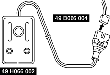
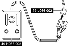
49 H066 002
Deployment tool
49 B066 004
Adapter harness

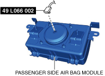
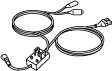
49 L066 002
Adapter harness
49 G066 003
Adapter harness
—
—
AIR BAG MODULE AND PRE-TENSIONER SEAT BELT DEPLOYMENT PROCEDURES [TWO-STEP DEPLOYMENT CONTROL SYSTEM]
id0810b1801100
Special Service Tool (SST)
|
49 H066 002
Deployment tool
|
|
49 B066 004
Adapter harness
|
|
49 L066 002
Adapter harness
|
|
|
49 G066 003
Adapter harness
|
|
—
|
—
|
||
Deployment Procedure for Inside of Vehicle
1. Inspect the SST (Deployment tool). (See INSPECTION OF SST (DEPLOYMENT TOOL) [TWO-STEP DEPLOYMENT CONTROL SYSTEM].)
2. Move the vehicle to an open space, away from strong winds, and close all of the vehicle doors and windows.
3. Switch the ignition off.
4. Disconnect the negative battery terminal and wait for 1 min or more. (See NEGATIVE BATTERY TERMINAL DISCONNECTION/CONNECTION.)
5. Follow the procedure below for operating (deploying) the applicable air bag module, pre-tensioner seat belt or lap pre-tensioner seat belt.
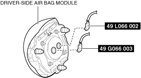
Driver-side air bag module
1. Remove the driver-side air bag module. (See DRIVER-SIDE AIR BAG MODULE REMOVAL [TWO-STEP DEPLOYMENT CONTROL SYSTEM].)
2. Connect the SST (Adapter harness) to the driver-side air bag module.
am6zzw00016122
|
3. Install the driver-side air bag module. (See DRIVER-SIDE AIR BAG MODULE INSTALLATION [TWO-STEP DEPLOYMENT CONTROL SYSTEM].)
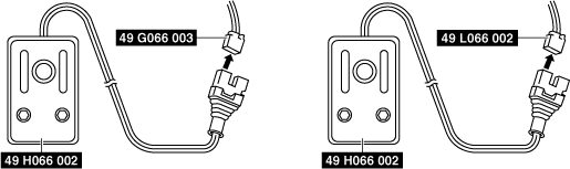
4. Connect the SST (Deployment tool) to the SST (Adapter harness).
am6zzw00016123
|
5. Connect the SST (Deployment tool) to the battery. Connect the power supply red clip to the positive battery terminal, and the black clip to the negative battery terminal.
6. Verify that the red lamp on the SST (Deployment tool) is illuminated.
7. Verify that all persons are standing at least 6 m {20 ft} away from the vehicle.
8. Press the activation switch on the SST (Deployment tool) connected with 49 L066 002 (a yellow connector) of the SST (Adapter harness), and after 3 s, press the activation switch on the other SST (Deployment tool) to operate (deploy) the air bag module (both inflators).
am6zzw00016124
|
9. Disconnect the SST (Deployment tool) from the SST (Adapter harness).
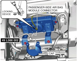
Passenger-side air bag module
1. Remove the glove compartment. (See GLOVE COMPARTMENT REMOVAL/INSTALLATION.)
2. Remove the cap.
am6zzw00016125
|
3. Using a flathead screwdriver, lift the locking device carefully, however do not remove it.
4. Disconnect the passenger-side air bag module connector.
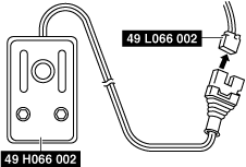
5. Connect the SST (Adapter harness) to the passenger-side air bag module.
6. Connect the SST (Deployment tool) to the SST (Adapter harness).
am6zzw00016126
|
7. Connect the SST (Deployment tool) to the battery. Connect the power supply red clip to the positive battery terminal, and the black clip to the negative battery terminal.
8. Verify that the red lamp on the SST (Deployment tool) is illuminated.
9. Verify that all persons are standing at least 6 m {20 ft} away from the vehicle.
10. Press the activation switch on the SST (Deployment tool) to operate (deploy) the air bag module.
am6zzw00016124
|
11. Disconnect the SST (Deployment tool) from the SST (Adapter harness).
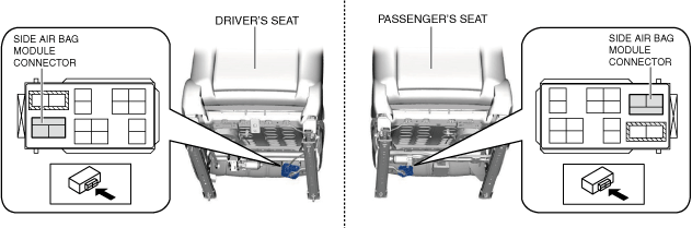
Side air bag module
1. Disconnect the side air bag module connector.
am6zzw00016127
|
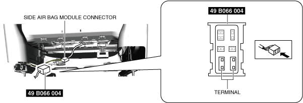
2. Connect the SST (Adapter harness) to the front seat connector.
am3zzw00018422
|
3. Connect the SST (Deployment tool) to the SST (Adapter harness).
am6zzw00016128
|
4. Connect the SST (Deployment tool) to the battery. Connect the power supply red clip to the positive battery terminal, and the black clip to the negative battery terminal.
5. Verify that the red lamp on the SST (Deployment tool) is illuminated.
6. Verify that all persons are standing at least 6 m {20 ft} away from the vehicle.
7. Press the activation switch on the SST (Deployment tool) to operate (deploy) the side air bag module.
am6zzw00016124
|
8. Disconnect the SST (Deployment tool) from the SST (Adapter harness).
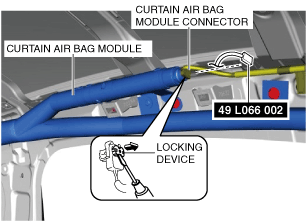
Curtain air bag module
1. Remove the following parts (4SD):
2. Remove the following parts (WGN):
3. Peel back the headliner.
4. Using a flathead screwdriver, lift the locking device carefully, however do not remove it.
am6zzw00016129
|
5. Disconnect the curtain air bag module connector.
6. Connect the SST (Adapter harness) to the curtain air bag module.
7. Connect the SST (Deployment tool) to the SST (Adapter harness).
am6zzw00016130
|
8. Connect the SST (Deployment tool) to the battery. Connect the power supply red clip to the positive battery terminal, and the black clip to the negative battery terminal.
9. Verify that the red lamp on the SST (Deployment tool) is illuminated.
10. Verify that all persons are standing at least 6 m {20 ft} away from the vehicle.
11. Press the activation switch on the SST (Deployment tool) to operate (deploy) the curtain air bag module.
am6zzw00016124
|
12. Disconnect the SST (Deployment tool) from the SST (Adapter harness).
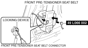
Front pre-tensioner seat belt
1. Remove the following parts:
2. Using a flathead screwdriver, lift the locking device carefully, however do not remove it.
am6zzw00016131
|
3. Disconnect the front pre-tensioner seat belt connector.
4. Connect the SST (Adapter harness) to the front pre-tensioner seat belt.
5. Connect the SST (Deployment tool) to the SST (Adapter harness).
am6zzw00016126
|
6. Connect the SST (Deployment tool) to the battery. Connect the power supply red clip to the positive battery terminal, and the black clip to the negative battery terminal.
7. Verify that the red lamp on the SST (Deployment tool) is illuminated.
8. Verify that all persons are standing at least 6 m {20 ft} away from the vehicle.
9. Press the activation switch on the SST (Deployment tool) to operate (deploy) the front pre-tensioner seat belt.
am6zzw00016124
|
10. Disconnect the SST (Deployment tool) from the SST (Adapter harness).
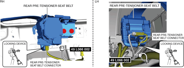
Rear pre-tensioner seat belt (4SD)
1. Remove the following parts:
2. Remove the rear seat belt (See REAR SEAT BELT REMOVAL/INSTALLATION.)
3. Using a flathead screwdriver, lift the locking device carefully, however do not remove it.
am6zzw00016132
|
4. Disconnect the mid-wiring harness connector.
5. Connect the SST (Adapter harness) to the rear pre-tensioner seat belt.
6. Install the rear seat belt (See REAR SEAT BELT REMOVAL/INSTALLATION.)
7. Connect the SST (Deployment tool) to the SST (Adapter harness).
am6zzw00016126
|
8. Connect the SST (Deployment tool) to the battery. Connect the power supply red clip to the positive battery terminal, and the black clip to the negative battery terminal.
9. Verify that the red lamp on the SST (Deployment tool) is illuminated.
10. Verify that all persons are standing at least 6 m {20 ft} away from the vehicle.
11. Press the activation switch on the SST (Deployment tool) to operate (deploy) the rear pre-tensioner seat belt.
am6zzw00016124
|
12. Disconnect the SST (Deployment tool) from the SST (Adapter harness).
Rear Pre-tensioner Seat Belt (WGN)
1. Remove the following parts:
2. Remove the rear seat belt (See REAR SEAT BELT REMOVAL/INSTALLATION.)
3. Using a flathead screwdriver, lift the locking device carefully, however do not remove it.
am6zzw00016133
|
4. Disconnect the rear pre-tensioner seat belt connector.
5. Connect the SST (Adapter harness) to the rear pre-tensioner seat belt.
6. Install the rear seat belt (See REAR SEAT BELT REMOVAL/INSTALLATION.)
7. Connect the SST (Deployment tool) to the SST (Adapter harness).
am6zzw00016126
|
8. Connect the SST (Deployment tool) to the battery. Connect the power supply red clip to the positive battery terminal, and the black clip to the negative battery terminal.
9. Verify that the red lamp on the SST (Deployment tool) is illuminated.
10. Verify that all persons are standing at least 6 m {20 ft} away from the vehicle.
11. Press the activation switch on the SST (Deployment tool) to operate (deploy) the rear pre-tensioner seat belt.
am6zzw00016124
|
12. Disconnect the SST (Deployment tool) from the SST (Adapter harness).
Deployment Procedure for Outside of Vehicle
1. Inspect the SST (Deployment tool). (See INSPECTION OF SST (DEPLOYMENT TOOL) [TWO-STEP DEPLOYMENT CONTROL SYSTEM].)
2. Switch the ignition off.
3. Disconnect the negative battery terminal and wait for 1 min or more. (See NEGATIVE BATTERY TERMINAL DISCONNECTION/CONNECTION.)
4. Follow the procedure below for operating (deploying) the applicable air bag module, pre-tensioner seat belt or lap pre-tensioner seat belt.
Driver-side air bag module
1. Remove the driver-side air bag module. (See DRIVER-SIDE AIR BAG MODULE REMOVAL [TWO-STEP DEPLOYMENT CONTROL SYSTEM].)
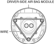
2. Wrap the wiring harness (cross section 1.25 mm2{0.002 in2} or more) at least three times around the position shown in the figure for the driver-side air bag module.
am6xuw00005946
|
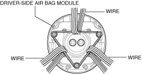
3. Wrap the wiring harness (cross section 1.25 mm2{0.002 in2} or more) at least four times around the position shown in the figure for the wrapped wiring harness.
am6zzw00016134
|
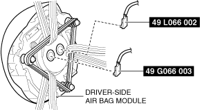
4. Connect the SST (Adapter harness) to the driver-side air bag module.
am6zzw00016135
|
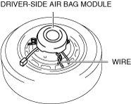
5. Place the driver-side air bag module on the center of the tire wheel with the padded surface facing up. To secure the air bag module to the tire wheel, wrap a wire (cross section 1.25 mm2{0.002 in2} or more) through the wheel and the bolt installation holes of the air bag module at least 4 times.
ac5uuw00002521
|
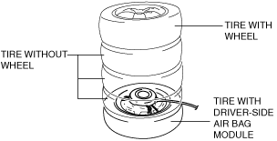
6. Stack three tires without wheels on top of the tire with the driver-side air bag module, and then stack another tire with a wheel on the very top.
ac5uuw00001495
|
7. Secure the tires with wire.
am3uuw00014010
|
8. Connect the SST (Deployment tool) to the SST (Adapter harness).
am6xuw00005949
|
9. Connect the SST (Deployment tool) to the battery. Connect the power supply red clip to the positive battery terminal, and the black clip to the negative battery terminal.
10. Verify that the red lamp on the SST (Deployment tool) is illuminated.
11. Verify that all persons are standing at least 6 m {20 ft} away from the driver-side air bag module.
12. Press the activation switch on the SST (Deployment tool) connected with 49 L066 002 (a yellow connector) of the SST (Adapter harness), and after 3 s, press the activation switch on the other SST (Deployment tool) to operate (deploy) the air bag module (both inflators).
am6zzw00016123
|
13. Disconnect the SST (Deployment tool) from the SST (Adapter harness).
Passenger-side air bag module
1. Remove the glove compartment. (See GLOVE COMPARTMENT REMOVAL/INSTALLATION.)
2. Remove the passenger-side air bag module. (See PASSENGER-SIDE AIR BAG MODULE REMOVAL/INSTALLATION [TWO-STEP DEPLOYMENT CONTROL SYSTEM].)
3. Connect the SST (Adapter harness) to the passenger-side air bag module.
am6zzw00016136
|
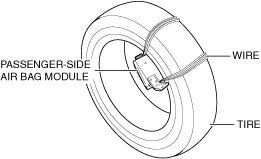
4. Place the padded surface of the passenger-side air bag module facing the center of the tire as shown in the figure. To secure the air bag module to the tire wheel, wrap a wire (cross section 1.25 mm2{0.002 in2} or more) through the tire and the bolt installation holes at least 4 times as shown in the figure.
am6xuw00005951
|
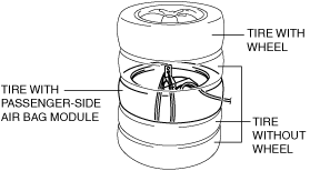
5. Stack the tire with the passenger-side air bag module on top of two tires without wheels. Stack a tire without a wheel on top of the tire with the passenger-side air bag module, and then stack another tire with a wheel on the very top.
am6xuw00001824
|
6. Secure the tires with wire.
am3uuw00014010
|
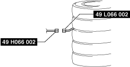
7. Connect the SST (Deployment tool) to the SST (Adapter harness).
am6zzw00016137
|
8. Connect the SST (Deployment tool) to the battery. Connect the power supply red clip to the positive battery terminal, and the black clip to the negative battery terminal.
9. Verify that the red lamp on the SST (Deployment tool) is illuminated.
10. Verify that all persons are standing at least 6 m {20 ft} away from the passenger-side air bag module.
11. Press the activation switch on the SST (Deployment tool) to operate (deploy) the air bag module.
am6zzw00016124
|
12. Disconnect the SST (Deployment tool) from the SST (Adapter harness).
Side air bag module
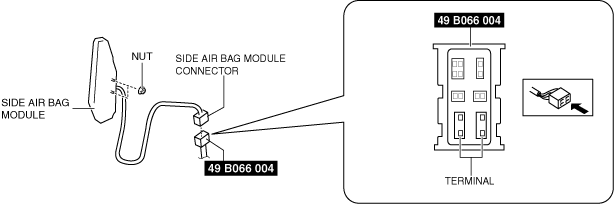
1. Remove the following parts:
2. Install the nuts.
am6zzw00014827
|
3. Connect the side air bag module connector to either one of the SST (Adapter harness) terminals shown in the figure.
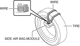
4. Put the side air bag module inside the tire and secure it to the tire by wrapping a wire (cross section of 1.25 mm2{0.002 in2} or more) through the tire and the bolt at least 4 times.
am6xuw00005954
|
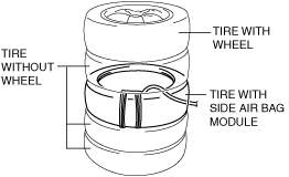
5. Stack the tire with the side air bag module on top of two tires without wheels. Stack a tire without a wheel on top of the tire with the side air bag module, and then stack another tire with a wheel on the very top.
ac5uuw00001503
|
6. Secure the tires with wire.
am3uuw00014010
|
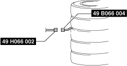
7. Connect the SST (Deployment tool) to the SST (Adapter harness).
am6xuw00005955
|
8. Connect the SST (Deployment tool) to the battery. Connect the power supply red clip to the positive battery terminal, and the black clip to the negative battery terminal.
9. Verify that the red lamp on the SST (Deployment tool) is illuminated.
10. Verify that all persons are standing at least 6 m {20 ft} away from the side air bag module.
11. Press the activation switch on the SST (Deployment tool) to operate (deploy) the side air bag module.
am6zzw00016124
|
12. Disconnect the SST (Deployment tool) from the SST (Adapter harness).
Curtain air bag module
1. Partially peel back the seaming welts.
2. Remove the following parts (4SD):
3. Remove the following parts (WGN):
4. Remove the curtain air bag module. (See CURTAIN AIR BAG MODULE REMOVAL/INSTALLATION [TWO-STEP DEPLOYMENT CONTROL SYSTEM].)
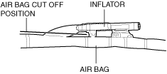
5. Cut off the air bag part of the curtain air bag module at the position shown in the figure.
am6xuw00005956
|
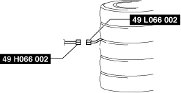
6. Connect the SST (Adapter harness) to the curtain air bag module.
am6zzw00016138
|
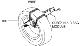
7. Secure the curtain air bag module to the tire, by wrapping a wire (cross section 1.25 mm2{0.002 in2} or more) through the tire and the bolt installation holes at least 4 times as shown in the figure.
am6xuw00005958
|
8. Stack the tire with the curtain air bag module on top of two tires without wheels. Stack a tire without a wheel on top of the tire with the curtain air bag module, and then stack another tire with a wheel on the very top.
am6xuw00005959
|
9. Secure the tires with wire.
am3uuw00014010
|
10. Connect the SST (Deployment tool) to the SST (Adapter harness).
am6zzw00016139
|
11. Connect the SST (Deployment tool) to the battery. Connect the power supply red clip to the positive battery terminal, and the black clip to the negative battery terminal.
12. Verify that the red lamp on the SST (Deployment tool) is illuminated.
13. Verify that all persons are standing at least 6 m {20 ft} away from the curtain air bag module.
14. Press the activation switch on the SST (Deployment tool) to operate (deploy) the curtain air bag module.
am6zzw00016124
|
15. Disconnect the SST (Deployment tool) from the SST (Adapter harness).
Front pre-tensioner seat belt
1. Remove the following parts:
2. Remove the front seat belt (See FRONT SEAT BELT REMOVAL/INSTALLATION.)
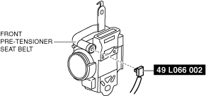
3. Connect the SST (Adapter harness) to the front pre-tensioner seat belt.
am6zzw00016140
|
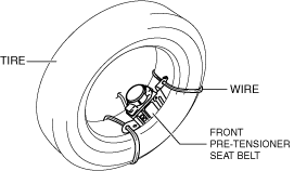
4. Put the front pre-tensioner seat belt inside the tire and secure it to the tire by wrapping a wire (cross section of 1.25 mm2{0.002 in2} or more) through the tire and the bolt installation holes at least 4 times.
am6zzw00016141
|
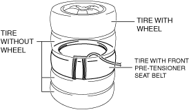
5. Stack the tire with the front pre-tensioner seat belt on to of two tires without wheels. Stack a tire without a wheel on top of the tire with the front pre-tensioner seat belt, and then stack another tire with a wheel on the very top.
am6zzw00016142
|
6. Secure the tires with wire.
am3uuw00014010
|
7. Connect the SST (Deployment tool) to the SST (Adapter harness).
am6xuw00005964
|
8. Connect the SST (Deployment tool) to the battery. Connect the power supply red clip to the positive battery terminal, and the black clip to the negative battery terminal.
9. Verify that the red lamp on the SST (Deployment tool) is illuminated.
10. Verify that all persons are standing at least 6 m {20 ft} away from the front pre-tensioner seat belt.
11. Press the activation switch on the SST (Deployment tool) to operate (deploy) the front pre-tensioner seat belt.
am6zzw00016124
|
12. Disconnect the SST (Deployment tool) from the SST (Adapter harness).
Rear pre-tensioner seat belt (4SD)
1. Remove the following parts:
2. Remove the rear seat belt (See REAR SEAT BELT REMOVAL/INSTALLATION.)
3. Using a flathead screwdriver, lift the locking device carefully, however do not remove it.
am6zzw00016132
|
4. Disconnect the mid-wiring harness connector.
5. Connect the SST (Adapter harness) to the rear pre-tensioner seat belt.
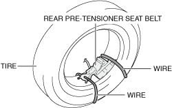
6. Put the rear pre-tensioner seat belt inside the tire and secure it to the tire by wrapping a wire (cross section of 1.25 mm2{0.002 in2} or more) through the tire and the bolt installation holes at least 4 times.
am6zzw00016143
|
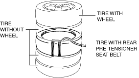
7. Stack the tire with the rear pre-tensioner seat belt on to of two tires without wheels. Stack a tire without a wheel on top of the tire with the rear pre-tensioner seat belt, and then stack another tire with a wheel on the very top.
am6zzw00016144
|
8. Secure the tires with wire.
am3uuw00014010
|
9. Connect the SST (Deployment tool) to the SST (Adapter harness).
am6xuw00005964
|
10. Connect the SST (Deployment tool) to the battery. Connect the power supply red clip to the positive battery terminal, and the black clip to the negative battery terminal.
11. Verify that the red lamp on the SST (Deployment tool) is illuminated.
12. Verify that all persons are standing at least 6 m {20 ft} away from the rear pre-tensioner seat belt.
13. Press the activation switch on the SST (Deployment tool) to operate (deploy) the rear pre-tensioner seat belt.
am6zzw00016124
|
14. Disconnect the SST (Deployment tool) from the SST (Adapter harness).
Rear pre-tensioner seat belt (WGN)
1. Remove the following parts:
2. Remove the rear seat belt (See REAR SEAT BELT REMOVAL/INSTALLATION.)
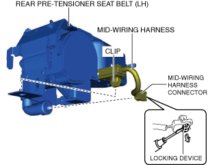
3. Using a flathead screwdriver, lift the locking device carefully, however do not remove it. (rear pre-tensioner seat belt (LH))
am6zzw00016145
|
4. Disconnect the mid-wiring harness connector. (rear pre-tensioner seat belt (LH))
5. Detach the clip and remove the mid-wiring harness. (rear pre-tensioner seat belt (LH))
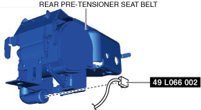
6. Connect the SST (Adapter harness) to the rear pre-tensioner seat belt.
am6zzw00016146
|
7. Put the rear pre-tensioner seat belt inside the tire and secure it to the tire by wrapping a wire (cross section of 1.25 mm2{0.002 in2} or more) through the tire and the bolt installation holes at least 4 times.
am6zzw00016147
|
8. Stack the tire with the rear pre-tensioner seat belt on to of two tires without wheels. Stack a tire without a wheel on top of the tire with the rear pre-tensioner seat belt, and then stack another tire with a wheel on the very top.
am6zzw00016144
|
9. Secure the tires with wire.
am3uuw00014010
|
10. Connect the SST (Deployment tool) to the SST (Adapter harness).
am6xuw00005964
|
11. Connect the SST (Deployment tool) to the battery. Connect the power supply red clip to the positive battery terminal, and the black clip to the negative battery terminal.
12. Verify that the red lamp on the SST (Deployment tool) is illuminated.
13. Verify that all persons are standing at least 6 m {20 ft} away from the rear pre-tensioner seat belt.
14. Press the activation switch on the SST (Deployment tool) to operate (deploy) the rear pre-tensioner seat belt.
am6zzw00016124
|
15. Disconnect the SST (Deployment tool) from the SST (Adapter harness).