TEMPERATURE SENSOR OF AIR FOR PTC/TEMPERATURE SENSOR OF REFRIGERANT LINE FOR ELECTRIC COMPRESSOR OUTLET REMOVAL/INSTALLATION [FULL-AUTO AIR CONDITIONER]
id0740a1704200
Replacement parts
|
Adhesive polyurethane
Quantity: 1
Location of use: Temperature sensor of air for PTC/temperature sensor of refrigerant line for electric compressor outlet
|
-
Warning
-
L.H.D.
1. Remove the selector lever knob. (See SELECTOR LEVER REMOVAL/INSTALLATION [A71M].)
2. Disconnect the negative lead-acid battery terminal. (See NEGATIVE LEAD-ACID BATTERY TERMINAL DISCONNECTION/CONNECTION.)
3. Remove the following parts:
- (1) Shift panel (See SHIFT PANEL REMOVAL/INSTALLATION.)
-
- (2) Console panel (See CONSOLE PANEL REMOVAL/INSTALLATION.)
-
- (3) Rear console (See REAR CONSOLE REMOVAL/INSTALLATION.)
-
- (4) Console bracket (See CONSOLE BRACKET REMOVAL/INSTALLATION.)
-
- (5) Front console upper panel (See FRONT CONSOLE UPPER PANEL REMOVAL/INSTALLATION.)
-
- (6) Console side panel (See CONSOLE SIDE PANEL REMOVAL/INSTALLATION.)
-
- (7) Front console box (See FRONT CONSOLE BOX REMOVAL/INSTALLATION.)
-
- (8) Side wall (See SIDE WALL REMOVAL/INSTALLATION.)
-
- (9) Front console (See FRONT CONSOLE REMOVAL/INSTALLATION.)
-
- (10) Passenger-side decoration panel (See DECORATION PANEL REMOVAL/INSTALLATION.)
-
- (11) Driver-side scuff plate (See SCUFF PLATE REMOVAL/INSTALLATION.)
-
- (12) Driver-side front side trim (See FRONT SIDE TRIM REMOVAL/INSTALLATION.)
-
- (13) Driver-side lower panel (See DRIVER-SIDE LOWER PANEL REMOVAL/INSTALLATION.)
-
- (14) Knee air bag module(See KNEE AIR BAG MODULE REMOVAL/INSTALLATION [TWO-STEP DEPLOYMENT CONTROL SYSTEM (E)].)
-
- (15) Center lower panel (See CENTER LOWER PANEL REMOVAL/INSTALLATION.)
-
4. Remove the driver-side front heat duct No.1. (See FRONT HEAT DUCT REMOVAL/INSTALLATION.)
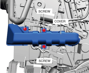
5. Remove the screws.
6. Remove the cover.
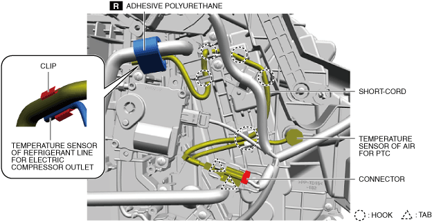
7. Disconnect the connectors.
8. Detach the short cord from the tab.
9. Detach the short cord from the hook.
10. Remove the adhesive polyurethane.
11. Remove the clip.
-
Caution
-
• When removing the temperature sensor of air for PTC, pull it out straight without twisting it. Otherwise, the A/C case could be damaged.
12. Remove the temperature sensor of air for PTC/temperature sensor of refrigerant line for electric compressor outlet. (See Temperature Sensor of Refrigerant Line For Electric Compressor Outlet Installation Note.)
13. Install in the reverse order of removal.
R.H.D.
1. Remove the selector lever knob. (See SELECTOR LEVER REMOVAL/INSTALLATION [A71M].)
2. Disconnect the negative lead-acid battery terminal and wait for 1 min or more. (See NEGATIVE LEAD-ACID BATTERY TERMINAL DISCONNECTION/CONNECTION.)
3. Remove the following parts:
- (1) Windshield wiper arm and blade (See WINDSHIELD WIPER ARM AND BLADE REMOVAL/INSTALLATION.)
-
- (2) Cowl grille (See COWL GRILLE REMOVAL/INSTALLATION.)
-
- (3) Side cowl grille (See COWL GRILLE REMOVAL/INSTALLATION.)
-
- (4) Shift panel (See SHIFT PANEL REMOVAL/INSTALLATION.)
-
- (5) Console panel (See CONSOLE PANEL REMOVAL/INSTALLATION.)
-
- (6) Rear console (See REAR CONSOLE REMOVAL/INSTALLATION.)
-
- (7) Console bracket (See CONSOLE BRACKET REMOVAL/INSTALLATION.)
-
- (8) Front console upper panel (See FRONT CONSOLE UPPER PANEL REMOVAL/INSTALLATION.)
-
- (9) Console side panel (See CONSOLE SIDE PANEL REMOVAL/INSTALLATION.)
-
- (10) Front console box (See FRONT CONSOLE BOX REMOVAL/INSTALLATION.)
-
- (11) Side wall (See SIDE WALL REMOVAL/INSTALLATION.)
-
- (12) Front console (See FRONT CONSOLE REMOVAL/INSTALLATION.)
-
- (13) Front pillar trim (See FRONT PILLAR TRIM REMOVAL/INSTALLATION.)
-
- (14) Scuff plate (See SCUFF PLATE REMOVAL/INSTALLATION.)
-
- (15) Front side trim (See FRONT SIDE TRIM REMOVAL/INSTALLATION.)
-
- (16) Passenger-side decoration panel (See DECORATION PANEL REMOVAL/INSTALLATION.)
-
- (17) Glove compartment (See GLOVE COMPARTMENT REMOVAL/INSTALLATION [(E)].)
-
- (18) Dashboard under cover (See DASHBOARD UNDER COVER REMOVAL/INSTALLATION.)
-
- (19) Passenger-side lower panel (See PASSENGER-SIDE LOWER PANEL REMOVAL [(E)].) (See PASSENGER-SIDE LOWER PANEL INSTALLATION [(E)].)
-
- (20) Driver-side lower panel (See DRIVER-SIDE LOWER PANEL REMOVAL/INSTALLATION.)
-
- (21) Knee air bag module(See KNEE AIR BAG MODULE REMOVAL/INSTALLATION [TWO-STEP DEPLOYMENT CONTROL SYSTEM (E)].)
-
- (22) Center lower panel (See CENTER LOWER PANEL REMOVAL/INSTALLATION.)
-
- (23) Driver-side decoration panel (See DECORATION PANEL REMOVAL/INSTALLATION.)
-
- (24) Driver-side air bag module(See DRIVER-SIDE AIR BAG MODULE REMOVAL [TWO-STEP DEPLOYMENT CONTROL SYSTEM (E)].)(See DRIVER-SIDE AIR BAG MODULE INSTALLATION [TWO-STEP DEPLOYMENT CONTROL SYSTEM (E)].)
-
- (25) Steering wheel (See STEERING WHEEL AND COLUMN REMOVAL/INSTALLATION.)
-
- (26) Upper column cover (See COLUMN COVER REMOVAL/INSTALLATION.)
-
- (27) Lower column cover (See COLUMN COVER REMOVAL/INSTALLATION.)
-
- (28) Clock spring(See CLOCK SPRING REMOVAL/INSTALLATION [TWO-STEP DEPLOYMENT CONTROL SYSTEM (E)].)
-
- (29) Light switch (See LIGHT SWITCH REMOVAL/INSTALLATION.)
-
- (30) Wiper and washer switch (See WIPER AND WASHER SWITCH REMOVAL/INSTALLATION.)
-
- (31) Joint cover (See STEERING WHEEL AND COLUMN REMOVAL/INSTALLATION.)
-
- (32) Steering column component (See STEERING WHEEL AND COLUMN REMOVAL/INSTALLATION.)
-
- (33) Meter hood (See METER HOOD REMOVAL/INSTALLATION.)
-
- (34) Instrument cluster(See INSTRUMENT CLUSTER REMOVAL/INSTALLATION [(E)].)
-
- (35) Center speaker grille (See SPEAKER GRILLE REMOVAL/INSTALLATION.)
-
- (36) Center display (See CENTER DISPLAY REMOVAL/INSTALLATION.)
-
- (37) Connectivity master unit (CMU)(See CONNECTIVITY MASTER UNIT (CMU) REMOVAL/INSTALLATION [(E)].)
-
- (38) Inverter (With AC power outlet) (See INVERTER REMOVAL/INSTALLATION.)
-
- (39) Driver monitoring camera unit(See DRIVER MONITORING CAMERA UNIT REMOVAL/INSTALLATION [(E)].)
-
- (40) Dashboard side cover(See DASHBOARD SIDE COVER REMOVAL/INSTALLATION [(E)].)
-
- (41) Dashboard(See DASHBOARD REMOVAL [(E)].)(See DASHBOARD INSTALLATION [(E)].)
-
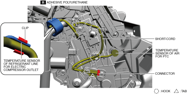
4. Disconnect the connectors.
5. Detach the short cord from the tab.
6. Detach the short cord from the hook.
7. Remove the adhesive polyurethane.
-
Caution
-
• When removing the temperature sensor of air for PTC, pull it out straight without twisting it. Otherwise, the A/C case could be damaged.
8. Remove the temperature sensor of air for PTC/temperature sensor of refrigerant line for electric compressor outlet. (See Temperature Sensor of Refrigerant Line For Electric Compressor Outlet Installation Note.)
9. Install in the reverse order of removal.
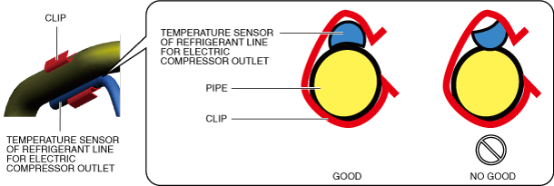
Temperature Sensor of Refrigerant Line For Electric Compressor Outlet Installation Note
1. Install the temperature sensor of refrigerant line for electric compressor outlet as shown in the figure.