ACTIVE DRIVING DISPLAY REMOVAL/INSTALLATION [(E)]
id0922007011x2
-
Warning
-
-
Caution
-
• When replacing the active driving display, perform the configuration to assure that the system operates correctly.
L.H.D.
1. To replace the active driving display, perform the following procedure.
- (1) Connect the M-MDS to the DLC-2.
-
- (2) Switch the main power ON (READY off).
-
- (3) Activate the M-MDS and perform the following procedure.
-
- 1) Press [Start] to start the vehicle identification.
-
- 2) Press the [Toolbox] tab.
-
- 3) Press the [Work Support] icon.
-
- 4) Press [Configuration].
-
- 5) Press [Run] to perform the configuration.
-
- 6) Press [ADD].
-
- 7) When [Install the new ECU] is displayed, move to the active driving display replacement procedure.
-
2. Remove the selector lever knob. (See SELECTOR LEVER REMOVAL/INSTALLATION [A71M].)
3. Disconnect the negative lead-acid battery terminal and wait for 1 min or more. (See NEGATIVE LEAD-ACID BATTERY TERMINAL DISCONNECTION/CONNECTION.)
4. Remove the following parts.
- (1) Windshield wiper arm and blade (See WINDSHIELD WIPER ARM AND BLADE REMOVAL/INSTALLATION.)
-
- (2) Cowl grille (See COWL GRILLE REMOVAL/INSTALLATION.)
-
- (3) Side cowl grille (See COWL GRILLE REMOVAL/INSTALLATION.)
-
- (4) Shift panel (See SHIFT PANEL REMOVAL/INSTALLATION.)
-
- (5) Console panel (See CONSOLE PANEL REMOVAL/INSTALLATION.)
-
- (6) Rear console (See REAR CONSOLE REMOVAL/INSTALLATION.)
-
- (7) Console bracket (See CONSOLE BRACKET REMOVAL/INSTALLATION.)
-
- (8) Front console upper panel (See FRONT CONSOLE UPPER PANEL REMOVAL/INSTALLATION.)
-
- (9) Console side panel (See CONSOLE SIDE PANEL REMOVAL/INSTALLATION.)
-
- (10) Front console box (See FRONT CONSOLE BOX REMOVAL/INSTALLATION.)
-
- (11) Side wall (See SIDE WALL REMOVAL/INSTALLATION.)
-
- (12) Front console (See FRONT CONSOLE REMOVAL/INSTALLATION.)
-
- (13) Front pillar trim (See FRONT PILLAR TRIM REMOVAL/INSTALLATION.)
-
- (14) Scuff plate (See SCUFF PLATE REMOVAL/INSTALLATION.)
-
- (15) Front side trim (See FRONT SIDE TRIM REMOVAL/INSTALLATION.)
-
- (16) Passenger's decoration panel (See DECORATION PANEL REMOVAL/INSTALLATION.)
-
- (17) Glove compartment (See GLOVE COMPARTMENT REMOVAL/INSTALLATION [(E)].)
-
- (18) Dashboard under cover (See DASHBOARD UNDER COVER REMOVAL/INSTALLATION.)
-
- (19) Passenger's lower panel (See PASSENGER-SIDE LOWER PANEL REMOVAL [(E)].) (See PASSENGER-SIDE LOWER PANEL INSTALLATION [(E)].)
-
- (20) Driver's lower panel (See DRIVER-SIDE LOWER PANEL REMOVAL/INSTALLATION.)
-
- (21) Knee air bag module (See KNEE AIR BAG MODULE REMOVAL/INSTALLATION [TWO-STEP DEPLOYMENT CONTROL SYSTEM (E)].)
-
- (22) Center lower panel (See CENTER LOWER PANEL REMOVAL/INSTALLATION.)
-
- (23) Driver's decoration panel (See DECORATION PANEL REMOVAL/INSTALLATION.)
-
- (24) Driver's air bag module (See DRIVER-SIDE AIR BAG MODULE REMOVAL [TWO-STEP DEPLOYMENT CONTROL SYSTEM (E)].) (See DRIVER-SIDE AIR BAG MODULE INSTALLATION [TWO-STEP DEPLOYMENT CONTROL SYSTEM (E)].)
-
- (25) Steering wheel (See STEERING WHEEL AND COLUMN REMOVAL/INSTALLATION.)
-
- (26) Upper column cover (See COLUMN COVER REMOVAL/INSTALLATION.)
-
- (27) Lower column cover (See COLUMN COVER REMOVAL/INSTALLATION.)
-
- (28) Clock spring (See CLOCK SPRING REMOVAL/INSTALLATION [TWO-STEP DEPLOYMENT CONTROL SYSTEM (E)].)
-
- (29) Wiper and washer switch (See WIPER AND WASHER SWITCH REMOVAL/INSTALLATION.)
-
- (30) Light switch (See LIGHT SWITCH REMOVAL/INSTALLATION.)
-
- (31) Joint cover (See STEERING WHEEL AND COLUMN REMOVAL/INSTALLATION.)
-
- (32) Steering column component (See STEERING WHEEL AND COLUMN REMOVAL/INSTALLATION.)
-
- (33) Meter hood (See METER HOOD REMOVAL/INSTALLATION.)
-
- (34) Instrument cluster (See INSTRUMENT CLUSTER REMOVAL/INSTALLATION [(E)].)
-
- (35) Center speaker grille (See SPEAKER GRILLE REMOVAL/INSTALLATION.)
-
- (36) Center display (See CENTER DISPLAY REMOVAL/INSTALLATION.)
-
- (37) Connectivity master unit (CMU) (See CONNECTIVITY MASTER UNIT (CMU) REMOVAL/INSTALLATION [(E)].)
-
- (38) Inverter (With AC power outlet) (See INVERTER REMOVAL/INSTALLATION.)
-
- (39) Driver monitoring camera unit (See DRIVER MONITORING CAMERA UNIT REMOVAL/INSTALLATION [(E)].)
-
- (40) Dashboard side cover (See DASHBOARD SIDE COVER REMOVAL/INSTALLATION [(E)].)
-
- (41) Dashboard (See DASHBOARD REMOVAL [(E)].) (See DASHBOARD INSTALLATION [(E)].)
-
- (42) Demister duct No.4 (See DASHBOARD DISASSEMBLY/ASSEMBLY.)
-
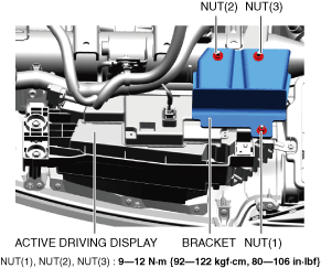
5. Remove nut (1).
6. Remove nut (2).
7. Remove nut (3).
8. Remove the bracket.
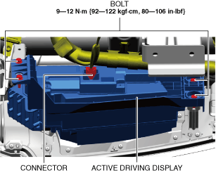
9. Disconnect the connector.
10. Remove the bolts.
-
Caution
-
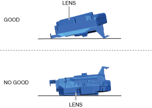
• When storing the active driving display, place it with the active driving display lens facing upward. Otherwise, the active driving display lens may be damaged and the active driving display may not operate normally.
11. Remove the active driving display.
12. Install in the reverse order of removal.
13. If the active driving display is replaced, perform the following procedure.
- (1) Return to the M-MDS operation and press [Continue].
-
- (2) When the M-MDS processing is completed, press [Next].
-
- (3) When the M-MDS processing is completed, press [Next].
-
- (4) Verify that the following conditions/operations are met/completed, mark the check boxes, and then press [Next].
-
-
• Switch the main power ON (READY off)
• Install battery charger to vehicle
• Lead-acid battery voltage: 11.6 V or more
• Connect power cable to M-MDS
• Front doors on both sides and liftgate are open
- (5) Press [Finish].
-
- (6) Switch the main power OFF.
-
- (7) Switch the main power ON (READY off) to complete the global central configuration (GCC) for the active driving display.
-
- (8) Clear the DTC. (See CLEARING DTC.)
-
R.H.D.
1. To replace the active driving display, perform the following procedure.
- (1) Connect the M-MDS to the DLC-2.
-
- (2) Switch the main power ON (READY off).
-
- (3) Activate the M-MDS and perform the following procedure.
-
- 1) Press [Start] to start the vehicle identification.
-
- 2) Press the [Toolbox] tab.
-
- 3) Press the [Work Support] icon.
-
- 4) Press [Configuration].
-
- 5) Press [Run] to perform the configuration.
-
- 6) Press [ADD].
-
- 7) When [Install the new ECU] is displayed, move to the active driving display replacement procedure.
-
2. Remove the selector lever knob. (See SELECTOR LEVER REMOVAL/INSTALLATION [A71M].)
3. Disconnect the negative lead-acid battery terminal and wait for 1 min or more. (See NEGATIVE LEAD-ACID BATTERY TERMINAL DISCONNECTION/CONNECTION.)
4. Remove the following parts.
- (1) Windshield wiper arm and blade (See WINDSHIELD WIPER ARM AND BLADE REMOVAL/INSTALLATION.)
-
- (2) Cowl grille (See COWL GRILLE REMOVAL/INSTALLATION.)
-
- (3) Side cowl grille (See COWL GRILLE REMOVAL/INSTALLATION.)
-
- (4) Shift panel (See SHIFT PANEL REMOVAL/INSTALLATION.)
-
- (5) Console panel (See CONSOLE PANEL REMOVAL/INSTALLATION.)
-
- (6) Rear console (See REAR CONSOLE REMOVAL/INSTALLATION.)
-
- (7) Console bracket (See CONSOLE BRACKET REMOVAL/INSTALLATION.)
-
- (8) Front console upper panel (See FRONT CONSOLE UPPER PANEL REMOVAL/INSTALLATION.)
-
- (9) Console side panel (See CONSOLE SIDE PANEL REMOVAL/INSTALLATION.)
-
- (10) Front console box (See FRONT CONSOLE BOX REMOVAL/INSTALLATION.)
-
- (11) Side wall (See SIDE WALL REMOVAL/INSTALLATION.)
-
- (12) Front console (See FRONT CONSOLE REMOVAL/INSTALLATION.)
-
- (13) Front pillar trim (See FRONT PILLAR TRIM REMOVAL/INSTALLATION.)
-
- (14) Scuff plate (See SCUFF PLATE REMOVAL/INSTALLATION.)
-
- (15) Front side trim (See FRONT SIDE TRIM REMOVAL/INSTALLATION.)
-
- (16) Passenger's decoration panel (See DECORATION PANEL REMOVAL/INSTALLATION.)
-
- (17) Glove compartment (See GLOVE COMPARTMENT REMOVAL/INSTALLATION [(E)].)
-
- (18) Dashboard under cover (See DASHBOARD UNDER COVER REMOVAL/INSTALLATION.)
-
- (19) Passenger's lower panel (See PASSENGER-SIDE LOWER PANEL REMOVAL [(E)].) (See PASSENGER-SIDE LOWER PANEL INSTALLATION [(E)].)
-
- (20) Driver's lower panel (See DRIVER-SIDE LOWER PANEL REMOVAL/INSTALLATION.)
-
- (21) Knee air bag module (See KNEE AIR BAG MODULE REMOVAL/INSTALLATION [TWO-STEP DEPLOYMENT CONTROL SYSTEM (E)].)
-
- (22) Center lower panel (See CENTER LOWER PANEL REMOVAL/INSTALLATION.)
-
- (23) Driver's decoration panel (See DECORATION PANEL REMOVAL/INSTALLATION.)
-
- (24) Driver's air bag module (See DRIVER-SIDE AIR BAG MODULE REMOVAL [TWO-STEP DEPLOYMENT CONTROL SYSTEM (E)].) (See DRIVER-SIDE AIR BAG MODULE INSTALLATION [TWO-STEP DEPLOYMENT CONTROL SYSTEM (E)].)
-
- (25) Steering wheel (See STEERING WHEEL AND COLUMN REMOVAL/INSTALLATION.)
-
- (26) Upper column cover (See COLUMN COVER REMOVAL/INSTALLATION.)
-
- (27) Lower column cover (See COLUMN COVER REMOVAL/INSTALLATION.)
-
- (28) Clock spring (See CLOCK SPRING REMOVAL/INSTALLATION [TWO-STEP DEPLOYMENT CONTROL SYSTEM (E)].)
-
- (29) Wiper and washer switch (See WIPER AND WASHER SWITCH REMOVAL/INSTALLATION.)
-
- (30) Light switch (See LIGHT SWITCH REMOVAL/INSTALLATION.)
-
- (31) Joint cover (See STEERING WHEEL AND COLUMN REMOVAL/INSTALLATION.)
-
- (32) Steering column component (See STEERING WHEEL AND COLUMN REMOVAL/INSTALLATION.)
-
- (33) Meter hood (See METER HOOD REMOVAL/INSTALLATION.)
-
- (34) Instrument cluster (See INSTRUMENT CLUSTER REMOVAL/INSTALLATION [(E)].)
-
- (35) Center speaker grille (See SPEAKER GRILLE REMOVAL/INSTALLATION.)
-
- (36) Center display (See CENTER DISPLAY REMOVAL/INSTALLATION.)
-
- (37) Connectivity master unit (CMU) (See CONNECTIVITY MASTER UNIT (CMU) REMOVAL/INSTALLATION [(E)].)
-
- (38) Inverter (With AC power outlet) (See INVERTER REMOVAL/INSTALLATION.)
-
- (39) Driver monitoring camera unit (See DRIVER MONITORING CAMERA UNIT REMOVAL/INSTALLATION [(E)].)
-
- (40) Dashboard side cover (See DASHBOARD SIDE COVER REMOVAL/INSTALLATION [(E)].)
-
- (41) Dashboard (See DASHBOARD REMOVAL [(E)].) (See DASHBOARD INSTALLATION [(E)].)
-
- (42) Demister duct No.4 (See DASHBOARD DISASSEMBLY/ASSEMBLY.)
-
5. Disconnect the connector.
6. Remove the bolts.
-
Caution
-
• When storing the active driving display, place it with the active driving display lens facing upward. Otherwise, the active driving display lens may be damaged and the active driving display may not operate normally.
7. Remove the active driving display.
8. Install in the reverse order of removal.
9. If the active driving display is replaced, perform the following procedure.
- (1) Return to the M-MDS operation and press [Continue].
-
- (2) When the M-MDS processing is completed, press [Next].
-
- (3) When the M-MDS processing is completed, press [Next].
-
- (4) Verify that the following conditions/operations are met/completed, mark the check boxes, and then press [Next].
-
-
• Switch the main power ON (READY off)
• Install battery charger to vehicle
• Lead-acid battery voltage: 11.6 V or more
• Connect power cable to M-MDS
• Front doors on both sides and liftgate are open
- (5) Press [Finish].
-
- (6) Switch the main power OFF.
-
- (7) Switch the main power ON (READY off) to complete the global central configuration (GCC) for the active driving display.
-
- (8) Clear the DTC. (See CLEARING DTC.)
-